2016-01-11 09:47:41
최근에 가장 많이 사용하는 통신 주파수라면 2.4Ghz가 아닌가 싶습니다. WiFi는 물론이고 블루투스나 RF통신 모두 2.4Ghz의 통신 주파수를 사용하는데 2.4Ghz통신의 장점이라면 높은 주파수로 인해 수신감도가 좋고 상대적으로 원거리에서도 서로 통신이 가능합니다. 또 TV리모컨과 같이 수신부를 향하지 않더라도 서로 통신이 가능하다는 점이 장점입니다.
아두이노에서는 WiFi나 Bluetooth, Zigbee 등 다양한 통신 방법을 지원하는데 하지만 대부분 사용하기 위해서는 몇 만원 이상의 비용을 지불하고 비싼 모듈을 구매하여 사용해야 합니다.
(물론 WiFi는 인터넷과 연결할 수 있고 Bluetooth는 스마트폰과 연결할 수 있는 각각의 장점이 있긴 합니다ㅎㅎ)
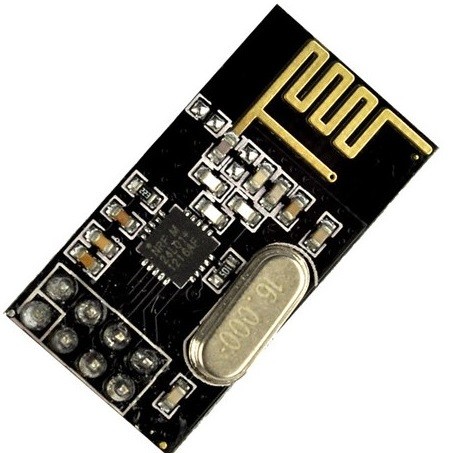
하지만 이 글에서 소개하는 nRF24L01모듈은 2.4Ghz로 통신하면서 상당히 저렴하고 크기도 작기 때문에 소형화와 통신 두가지를 모두 원하는 Maker에게는 최적의 모듈이 아닌가 생각합니다.
Kocoafab에서는 이 모듈을 샘플전자를 통해 약 3천~4천원 사이의 가격으로 구매했던 기억이 납니다.
상당히 저가이기때문에 사용하다 망가져도 상대적으로 부담이 적고, 성능또한 가격에 비해서 괜찮은 통신 유효거리를 보이기 때문에 사용방법만 익힌다면 보편적으로 사용해도 괜찮을 센서입니다.
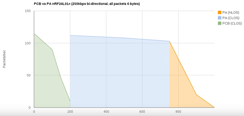
<위 센서인 PCB버전의 경우에는 200m정도까지의 통신 거리를 보인다>
이번 글에서는 WiFi나 블루투스에 비해 상대적으로 덜 알려져 있지만 통신모듈로 사용할 수 있는 nRF24L01모듈을 알아보고 간단한 튜토리얼을 사용해 보겠습니다.
| NO | 부품명 | 수량 | 상세설명 |
| 1 | 오렌지 보드 | 1 | 아두이노UNO 호환 |
| 2 | nRF24L01 모듈 | 1 | 2.4Ghz RF통신 |
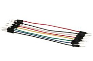
| 3 | 점퍼케이블 | 10 | 암수 케이블(F/M cable) |
| 부품명 | 오렌지 보드 | nRF24L01 모듈 | 점퍼케이블 |
| 파트 | 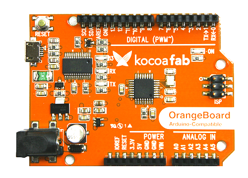 |
 |
 |
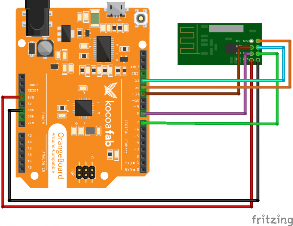
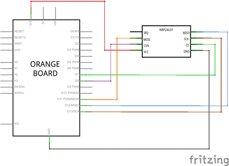
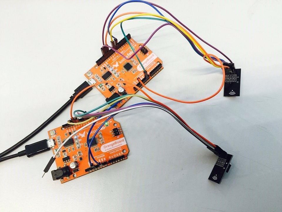
핀 연결 표
| IRQ | 연결없음 | MISO | D12 |
| MOSI | D11 | SCK | D13 |
| CSN | D8 | CE | D7 |
| VCC | 3.3V | GND | GND |
※ 전류는 5V가 아닌 3.3V에 연결해주셔야 합니다. 5V연결할 경우 모듈이 망가질 수 있으니 주의 하세요!
연결은 SPI통신으로 MISO핀과 MOSI핀을 사용합니다. 그리고 CSN핀과 CE핀은 소스코드상에서 변경가능합니다.
/*
* Getting Started example sketch for nRF24L01+ radios
* This is a very basic example of how to send data from one node to another
* Updated: Dec 2014 by TMRh20
*/

#include <SPI.h>
#include "RF24.h"

// Set this radio as radio number 0 or 1
bool radioNumber = 0;
// Hardware configuration: Set up nRF24L01 radio on SPI bus plus pins 7 & 8
RF24 radio(7,8);

byte addresses[][6] = {"1Node","2Node"};

// Used to control whether this node is sending or receiving
bool role = 0;

void setup() {
        Serial.begin(115200);
        Serial.println(F("RF24/examples/GettingStarted"));
        Serial.println(F("*** PRESS 'T' to begin transmitting to the other node"));

        radio.begin();

        // Set the PA Level low to prevent power supply related issues since this is a
        // getting_started sketch, and the likelihood of close proximity of the devices. RF24_PA_MAX is default.
        radio.setPALevel(RF24_PA_LOW);

        // Open a writing and reading pipe on each radio, with opposite addresses
        if (radioNumber) {
                radio.openWritingPipe((uint64_t)addresses[1]);
                radio.openReadingPipe(1,(uint64_t)addresses[0]);
        } else {
                radio.openWritingPipe((uint64_t)addresses[0]);
                radio.openReadingPipe(1,(uint64_t)addresses[1]);
        }

        // Start the radio listening for data
        radio.startListening();
}

void loop() {

        // Ping Out Role
        if (role == 1) {
                // First, stop listening so we can talk.
            radio.stopListening();
                Serial.println(F("Now sending"));

                // Take the time, and send it.  This will block until complete
                unsigned long time = micros();
                if (!radio.write( &time, sizeof(unsigned long) )) {
                        Serial.println(F("failed"));
                }

        // Now, continue listening
                radio.startListening();

            // Set up a timeout period, get the current microseconds
                unsigned long started_waiting_at = micros();
                // Set up a variable to indicate if a response was received or not
                boolean timeout = false;

            // While nothing is received
                while ( ! radio.available() ) {
                        // If waited longer than 200ms, indicate timeout and exit while loop
                        if (micros() - started_waiting_at > 200000 ) {
                                timeout = true;
                                break;
                        }
                }

        // Describe the results
                if ( timeout ) {
                        Serial.println(F("Failed, response timed out."));
                } else {
                        // Grab the response, compare, and send to debugging spew
                        unsigned long got_time;
                        radio.read( &got_time, sizeof(unsigned long) );
                        unsigned long time = micros();

                        // Spew it
                        Serial.print(F("Sent "));
                        Serial.print(time);
                        Serial.print(F(", Got response "));
                        Serial.print(got_time);
                        Serial.print(F(", Round-trip delay "));
                        Serial.print(time-got_time);
                        Serial.println(F(" microseconds"));
            }

                // Try again 1s later
                delay(1000);
        }


        // Pong Back Role
        if ( role == 0 ) {
                // Variable for the received timestamp
                unsigned long got_time;

                if ( radio.available()) {
                        // While there is data ready
                        while (radio.available()) {
                                // Get the payload
                                radio.read( &got_time, sizeof(unsigned long) );
                        }
                     // First, stop listening so we can talk
                        radio.stopListening();
                        // Send the final one back.
                        radio.write( &got_time, sizeof(unsigned long) );
                        // Now, resume listening so we catch the next packets.
                        radio.startListening();
                        Serial.print(F("Sent response "));
                        Serial.println(got_time);
                }
         }

        // Change Roles via Serial Commands
        if ( Serial.available() ) {
                char c = toupper(Serial.read());
                if ( c == 'T' && role == 0 ) {
                        Serial.println(F("*** CHANGING TO TRANSMIT ROLE -- PRESS 'R' TO SWITCH BACK"));
                        // Become the primary transmitter (ping out)
                        role = 1;

                } else {
                    if ( c == 'R' && role == 1 ) {
                                Serial.println(F("*** CHANGING TO RECEIVE ROLE -- PRESS 'T' TO SWITCH BACK"));
                                // Become the primary receiver (pong back)
                                role = 0;
                                radio.startListening();
                        }
                }
        }
}
nRF24L01모듈을 사용하기 위한 라이브러리는 여러가지가 있지만 이 글에서는 RF24라이브러리를 사용하여 설명하겠습니다.
nRF24L01모듈은 SPI통신을 사용하며 양방향통신을 지원합니다.
위 소스는 하나의 소스로 두 가지 아두이노의 모드를 조절할 수 있습니다.
하나의 아두이노는 Ping역할(신호는 보내고 Pong의 응답을 받는 역할)을 하고 다른 하나의 아두이노는 Pong역할(Ping에서 보내는 신호를 받고 응답하는 역할)을 합니다. PingPong 즉 탁구와 같이 한쪽에서 신호를 보내면 다른 한쪽은 쳐내는 역할을 반복적으로 수행합니다.
위 역할을 정하기 위해서는 소스 상단의 아래 코드를 각 역할에 따라 0과 1로 변경해주셔야 합니다.(Transmit역할과 Receive역할은 시리얼 모니터에서 변경가능합니다.)
/****************** User Config ***************************/
/***      Set this radio as radio number 0 or 1         ***/
bool radioNumber = 0;
위 하드웨어making부분에서 CSN핀과 CE핀은 코드내에서 조정이 가능하다 했었는데 아래 코드에서 변경이 가능합니다. Default값으로 설정된 값은 7번핀과 8번핀입니다.
/* Hardware configuration: Set up nRF24L01 radio on SPI bus plus pins 7 & 8 */
RF24 radio(7,8);
/**********************************************************/
또 위 코드에서는 파이프통신을 사용합니다.
파이프 통신이랑 통신 방법이 슈퍼마리오에 나오는 들어가고 나오는 파이프와 같다하여 붙여진 이름입니다.

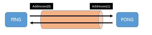
파이프의 각 입구마다 주소를 정해놓고 보내는 쪽과 받는쪽에서는 그 주소를 통해 통신하게 됩니다.
아래의 그림을 들어 예를 들면 PING은 Addressed[0]에서 Addresses[1]로 보내게 되면 Addresses[1]에 있는 PONG에게로 데이터가 전달됩니다.
반대로 Addresses[1]에서 Addresses[0]으로 데이터를 보내면 PING은 PING으로 데이터를 전송하게 됩니다.
nRF24L01모듈에서는 이러한 파이프를 6개까지 생성하여 하나의 RX와 최대 6개의 TX가 하나의 채널에서 통신이 가능합니다.
nRF24L01모듈은 또 양방향통신을 지원한다고는 하지만 Half duplex통신을 지원합니다.
Half duplex란 양방향통신 중 하나의 방법으로 한 사람이 데이터를 전송할 때 다른 한사람은 듣고만 있어야하는 불완전한 통신방법입니다.
실생활에서는 군대에서 사용하는 무전기를 생각하시면 됩니다.
Half duplex로 인해 위 소스에서는 데이터를 보낼 때 아래 코드와 같이 stopListening()이 선행되는것을 볼 수 있습니다. 데이터를 읽는 것을 계속한다면 데이터를 보낼 수 없기 때문에 데이터의 수신을 중단한다음 데이터를 전송하고 그 다음 다시 수신을 시작하게 됩니다.
      radio.stopListening();                                        // First, stop listening so we can talk
      radio.write( &got_time, sizeof(unsigned long) );              // Send the final one back.
      radio.startListening();

kocoafabeditor 
항상 진취적이고, 새로운 것을 추구하는 코코아팹 에디터입니다!
 nRF24L01, 아두이노, 오렌지보드


