
앰비라이트(Amblight) 만들기
2014-11-24 17:29:25
개요
앰비라이트 (Amblight)는 Ambient + Light 의 합성어로 주변광을 뜻하는데요,TV나 모니터 사각 테두리를 LED로 두르고, 현재 화면의 색상 정보를 캡쳐하여
LED로 배열하여 출력하는 원리입니다.
아래의 영상을 통해 그 효과를 감상해 보세요 !
출처 : Amblight - Youtube
앰비라이트는 영상에서처럼 화면 주변부에 현재 출력 화면과 동일한 색상의 빛을 출력함으로써
더욱 몰입도 있는 시각효과를 만들어 줍니다.
음향과 함께 사용되면 영화나 게임을 할 때 그 감동이 두 배가 되니,
프로젝트를 통해 함께 만들어보고, 집에 있는 모니터나 TV 규격에 맞추어 더 크고 멋지게 만들어 보세요!
앰비라이트는 영상에서처럼 화면 주변부에 현재 출력 화면과 동일한 색상의 빛을 출력함으로써
더욱 몰입도 있는 시각효과를 만들어 줍니다.
음향과 함께 사용되면 영화나 게임을 할 때 그 감동이 두 배가 되니,
프로젝트를 통해 함께 만들어보고, 집에 있는 모니터나 TV 규격에 맞추어 더 크고 멋지게 만들어 보세요!


미리보기 동영상
시작전 개념 이해하기
부품목록

| NO | 부품명 | 수량 | 상세설명 |
| 1 | 오렌지 보드 | 1 | 아두이노 호환보드 |
| 2 | RGB LED | 20 | WS2801 LED컨트롤러가 내장된 LED를 사용합니다. |
| 3 | 외부 전원 | 1 | 9-12V |
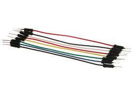
| 4 | 점퍼 케이블 | 3 | M/M |
| 5 | 배럴 잭 | 1 | 2.1mm 스크류 암커넥터 |
| 6 | 종이 테이프 | 1 | LED및 전선 고정용 |
| 부품명 | 오렌지보드 | RGB LED | 외부 전원 | 점퍼 케이블 | 배럴 잭 |
| 사진 | 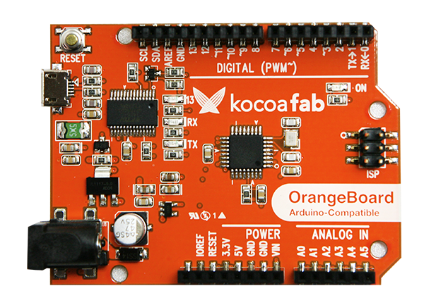 X1 X1 |
 x20 x20 |
 x1 x1 |
 x3 x3 |
 x3 x3 |
| 부품명 | 종이 테이프 |
| 사진 |  x1 x1 |
이 프로젝트에 사용된 LED는 WS2801컨트롤러가 내장된 RGB LED 20개가 연결된 제품을 사용하였습니다.
하드웨어 Making
회로도

출처 : Adafruit
사용하시는 RGB LED의 갯수와 종류에 맞는 외부 전원을 사용하세요.


출처: WS2801이 내장된 RGB LED 브레이크아웃 보드 - sparkfun
위 사진의 제품처럼 WS2801 LED 드라이버칩이 내장된 LED를 사용해 주세요.

노란색 선 (SPI MOSI / DO)을 11번 핀에
초록색 선 (SPI CLOCK /CO)을 13번 핀에
파란색 선 (GROUND)을 GND에 연결합니다.

가장 끝쪽 LED에서 전원을 공급 받습니다.

인풋과 아웃풋에 따른 연결 방향을 주의해 주세요.
전원 > LED 모듈 > 아두이노

모니터의 모양에따라 적절히 LED의 갯수를 배열합니다.

종이 테이프를 이용하여 부착합니다.
종이 박스나 포맥스를 이용하여 견고한 고정대를 만들어 봐도 좋겠습니다.

소프트웨어 Coding
본 프로젝트에서는 아두이노와 프로세싱을 사용합니다.아래의 링크를 통해 라이브러리를 받습니다.
파일 내려받기

압축을 해제하면 '아두이노'폴더 와 프로세싱 폴더가 있습니다.
하위 폴더를 아두이노와 프로세싱 라이브러리 폴더에 옮겨주세요.
Window) 문서 > Arduino > Libraries
문서 > Processing > Libraries
Mac OSX) Documents > Arduino > Libararies
Documents > Processing > Libararies
아래의 코드를 아두이노에 업로드 합니다.
//출처 : www.adafruit.com
// 이 코드는 디지털 기반으로 호스트 컴퓨터와 WS2801간의 "연결" 코드입니다.
// 아두이노의 램 용량 제한으로 인한 LED 연결에 제약이 있을 수 있습니다.
// LED data 와 clock lines 은 Arduino의 SPI output에 연결됩니다.
// 기본적으로 아두이노의 SPI OUTPUT 은 디지털 핀 11 입니다.
// Clock은 디지털 핀 13입니다.
// LED 의 그라운드는 아두이노의 그라운드와 연결되어야 합니다.


//   <http://www.gnu.org/licenses/>.


import java.awt.*;
import java.awt.image.*;
import processing.serial.*;

// CONFIGURABLE PROGRAM CONSTANTS --------------------------------------------

// Minimum LED brightness; some users prefer a small amount of backlighting
// at all times, regardless of screen content.  Higher values are brighter,
// or set to 0 to disable this feature.

static final short minBrightness = 120;

// LED transition speed; it's sometimes distracting if LEDs instantaneously
// track screen contents (such as during bright flashing sequences), so this
// feature enables a gradual fade to each new LED state.  Higher numbers yield
// slower transitions (max of 255), or set to 0 to disable this feature
// (immediate transition of all LEDs).

static final short fade = 75;

// Pixel size for the live preview image.

static final int pixelSize = 20;

// Depending on many factors, it may be faster either to capture full
// screens and process only the pixels needed, or to capture multiple
// smaller sub-blocks bounding each region to be processed.  Try both,
// look at the reported frame rates in the Processing output console,
// and run with whichever works best for you.

static final boolean useFullScreenCaps = true;

// Serial device timeout (in milliseconds), for locating Arduino device
// running the corresponding LEDstream code.  See notes later in the code...
// in some situations you may want to entirely comment out that block.

static final int timeout = 5000; // 5 seconds

// PER-DISPLAY INFORMATION ---------------------------------------------------

// This array contains details for each display that the software will
// process.  If you have screen(s) attached that are not among those being
// "Adalighted," they should not be in this list.  Each triplet in this
// array represents one display.  The first number is the system screen
// number...typically the "primary" display on most systems is identified
// as screen #1, but since arrays are indexed from zero, use 0 to indicate
// the first screen, 1 to indicate the second screen, and so forth.  This
// is the ONLY place system screen numbers are used...ANY subsequent
// references to displays are an index into this list, NOT necessarily the
// same as the system screen number.  For example, if you have a three-
// screen setup and are illuminating only the third display, use '2' for
// the screen number here...and then, in subsequent section, '0' will be
// used to refer to the first/only display in this list.
// The second and third numbers of each triplet represent the width and
// height of a grid of LED pixels attached to the perimeter of this display.
// For example, '9,6' = 9 LEDs across, 6 LEDs down.

static final int displays[][] = new int[][] {
   {0,7,5} // Screen 0, 7 LEDs across, 5 LEDs down
//,{1,9,6} // Screen 1, also 9 LEDs across and 6 LEDs down
};

// PER-LED INFORMATION -------------------------------------------------------

// This array contains the 2D coordinates corresponding to each pixel in the
// LED strand, in the order that they're connected (i.e. the first element
// here belongs to the first LED in the strand, second element is the second
// LED, and so forth).  Each triplet in this array consists of a display
// number (an index into the display array above, NOT necessarily the same as
// the system screen number) and an X and Y coordinate specified in the grid
// units given for that display.  {0,0,0} is the top-left corner of the first
// display in the array.
// For our example purposes, the coordinate list below forms a ring around
// the perimeter of a single screen, with a one pixel gap at the bottom to
// accommodate a monitor stand.  Modify this to match your own setup:

static final int leds[][] = new int[][] {
 {0,3,4}, {0,2,4}, {0,1,4}, {0,0,4}, // Bottom edge, left half
  {0,0,3}, {0,0,2}, {0,0,1}, // Left edge
  {0,0,0}, {0,1,0}, {0,2,0}, {0,3,0}, {0,4,0}, // Top edge
           {0,5,0}, {0,6,0},  // More top edge
  {0,6,1}, {0,6,2}, {0,6,3}, {0,6,4}, // Right edge
 {0,5,4}, {0,4,4}  // Bottom edge, right half
/* Hypothetical second display has the same arrangement as the first.
   But you might not want both displays completely ringed with LEDs;
   the screens might be positioned where they share an edge in common.
 ,{1,3,5}, {1,2,5}, {1,1,5}, {1,0,5}, // Bottom edge, left half
  {1,0,4}, {1,0,3}, {1,0,2}, {1,0,1}, // Left edge
  {1,0,0}, {1,1,0}, {1,2,0}, {1,3,0}, {1,4,0}, // Top edge
           {1,5,0}, {1,6,0}, {1,7,0}, {1,8,0}, // More top edge
  {1,8,1}, {1,8,2}, {1,8,3}, {1,8,4}, // Right edge
  {1,8,5}, {1,7,5}, {1,6,5}, {1,5,5}  // Bottom edge, right half
*/
};

// GLOBAL VARIABLES ---- You probably won't need to modify any of this -------

byte[]           serialData  = new byte[6 + leds.length * 3];
short[][]        ledColor    = new short[leds.length][3],
                 prevColor   = new short[leds.length][3];
byte[][]         gamma       = new byte[256][3];
int              nDisplays   = displays.length;
Robot[]          bot         = new Robot[displays.length];
Rectangle[]      dispBounds  = new Rectangle[displays.length],
                 ledBounds;  // Alloc'd only if per-LED captures
int[][]          pixelOffset = new int[leds.length][256],
                 screenData; // Alloc'd only if full-screen captures
PImage[]         preview     = new PImage[displays.length];
Serial           port;
DisposeHandler   dh; // For disabling LEDs on exit

// INITIALIZATION ------------------------------------------------------------

void setup() {
  GraphicsEnvironment     ge;
  GraphicsConfiguration[] gc;
  GraphicsDevice[]        gd;
  int                     d, i, totalWidth, maxHeight, row, col, rowOffset;
  int[]                   x = new int[16], y = new int[16];
  float                   f, range, step, start;

  dh = new DisposeHandler(this); // Init DisposeHandler ASAP

  // Open serial port.  As written here, this assumes the Arduino is the
  // first/only serial device on the system.  If that's not the case,
  // change "Serial.list()[0]" to the name of the port to be used:
  port = new Serial(this, Serial.list()[2], 115200);
  // Alternately, in certain situations the following line can be used
  // to detect the Arduino automatically.  But this works ONLY with SOME
  // Arduino boards and versions of Processing!  This is so convoluted
  // to explain, it's easier just to test it yourself and see whether
  // it works...if not, leave it commented out and use the prior port-
  // opening technique.
  // port = openPort();
  // And finally, to test the software alone without an Arduino connected,
  // don't open a port...just comment out the serial lines above.

  // Initialize screen capture code for each display's dimensions.
  dispBounds = new Rectangle[displays.length];
  if(useFullScreenCaps == true) {
    screenData = new int[displays.length][];
    // ledBounds[] not used
  } else {
    ledBounds  = new Rectangle[leds.length];
    // screenData[][] not used
  }
  ge = GraphicsEnvironment.getLocalGraphicsEnvironment();
  gd = ge.getScreenDevices();
  if(nDisplays > gd.length) nDisplays = gd.length;
  totalWidth = maxHeight = 0;
  for(d=0; d<nDisplays; d++) { // For each display...
    try {
      bot[d] = new Robot(gd[displays[d][0]]);
    }
    catch(AWTException e) {
      System.out.println("new Robot() failed");
      continue;
    }
    gc              = gd[displays[d][0]].getConfigurations();
    dispBounds[d]   = gc[0].getBounds();
    dispBounds[d].x = dispBounds[d].y = 0;
    preview[d]      = createImage(displays[d][1], displays[d][2], RGB);
    preview[d].loadPixels();
    totalWidth     += displays[d][1];
    if(d > 0) totalWidth++;
    if(displays[d][2] > maxHeight) maxHeight = displays[d][2];
  }

  // Precompute locations of every pixel to read when downsampling.
  // Saves a bunch of math on each frame, at the expense of a chunk
  // of RAM.  Number of samples is now fixed at 256; this allows for
  // some crazy optimizations in the downsampling code.
  for(i=0; i<leds.length; i++) { // For each LED...
    d = leds[i][0]; // Corresponding display index

    // Precompute columns, rows of each sampled point for this LED
    range = (float)dispBounds[d].width / (float)displays[d][1];
    step  = range / 16.0;
    start = range * (float)leds[i][1] + step * 0.5;
    for(col=0; col<16; col++) x[col] = (int)(start + step * (float)col);
    range = (float)dispBounds[d].height / (float)displays[d][2];
    step  = range / 16.0;
    start = range * (float)leds[i][2] + step * 0.5;
    for(row=0; row<16; row++) y[row] = (int)(start + step * (float)row);

    if(useFullScreenCaps == true) {
      // Get offset to each pixel within full screen capture
      for(row=0; row<16; row++) {
        for(col=0; col<16; col++) {
          pixelOffset[i][row * 16 + col] =
            y[row] * dispBounds[d].width + x[col];
        }
      }
    } else {
      // Calc min bounding rect for LED, get offset to each pixel within
      ledBounds[i] = new Rectangle(x[0], y[0], x[15]-x[0]+1, y[15]-y[0]+1);
      for(row=0; row<16; row++) {
        for(col=0; col<16; col++) {
          pixelOffset[i][row * 16 + col] =
            (y[row] - y[0]) * ledBounds[i].width + x[col] - x[0];
        }
      }
    }
  }

  for(i=0; i<prevColor.length; i++) {
    prevColor[i][0] = prevColor[i][1] = prevColor[i][2] =
      minBrightness / 3;
  }

  // Preview window shows all screens side-by-side
  size(totalWidth * pixelSize, maxHeight * pixelSize, JAVA2D);
  noSmooth();

  // A special header / magic word is expected by the corresponding LED
  // streaming code running on the Arduino.  This only needs to be initialized
  // once (not in draw() loop) because the number of LEDs remains constant:
  serialData[0] = 'A';                              // Magic word
  serialData[1] = 'd';
  serialData[2] = 'a';
  serialData[3] = (byte)((leds.length - 1) >> 8);   // LED count high byte
  serialData[4] = (byte)((leds.length - 1) & 0xff); // LED count low byte
  serialData[5] = (byte)(serialData[3] ^ serialData[4] ^ 0x55); // Checksum

  // Pre-compute gamma correction table for LED brightness levels:
  for(i=0; i<256; i++) {
    f           = pow((float)i / 255.0, 2.8);
    gamma[i][0] = (byte)(f * 255.0);
    gamma[i][1] = (byte)(f * 240.0);
    gamma[i][2] = (byte)(f * 220.0);
  }
}

// Open and return serial connection to Arduino running LEDstream code.  This
// attempts to open and read from each serial device on the system, until the
// matching "Ada\n" acknowledgement string is found.  Due to the serial
// timeout, if you have multiple serial devices/ports and the Arduino is late
// in the list, this can take seemingly forever...so if you KNOW the Arduino
// will always be on a specific port (e.g. "COM6"), you might want to comment
// out most of this to bypass the checks and instead just open that port
// directly!  (Modify last line in this method with the serial port name.)

Serial openPort() {
  String[] ports;
  String   ack;
  int      i, start;
  Serial   s;

  ports = Serial.list(); // List of all serial ports/devices on system.

  for(i=0; i<ports.length; i++) { // For each serial port...
    System.out.format("Trying serial port %s\n",ports[i]);
    try {
      s = new Serial(this, ports[i], 115200);
    }
    catch(Exception e) {
      // Can't open port, probably in use by other software.
      continue;
    }
    // Port open...watch for acknowledgement string...
    start = millis();
    while((millis() - start) < timeout) {
      if((s.available() >= 4) &&
        ((ack = s.readString()) != null) &&
        ack.contains("Ada\n")) {
          return s; // Got it!
      }
    }
    // Connection timed out.  Close port and move on to the next.
    s.stop();
  }

  // Didn't locate a device returning the acknowledgment string.
  // Maybe it's out there but running the old LEDstream code, which
  // didn't have the ACK.  Can't say for sure, so we'll take our
  // changes with the first/only serial device out there...
  return new Serial(this, ports[0], 115200);
}


// PER_FRAME PROCESSING ------------------------------------------------------

void draw () {
  BufferedImage img;
  int           d, i, j, o, c, weight, rb, g, sum, deficit, s2;
  int[]         pxls, offs;

  if(useFullScreenCaps == true ) {
    // Capture each screen in the displays array.
    for(d=0; d<nDisplays; d++) {
      img = bot[d].createScreenCapture(dispBounds[d]);
      // Get location of source pixel data
      screenData[d] =
        ((DataBufferInt)img.getRaster().getDataBuffer()).getData();
    }
  }

  weight = 257 - fade; // 'Weighting factor' for new frame vs. old
  j      = 6;          // Serial led data follows header / magic word

  // This computes a single pixel value filtered down from a rectangular
  // section of the screen.  While it would seem tempting to use the native
  // image scaling in Processing/Java, in practice this didn't look very
  // good -- either too pixelated or too blurry, no happy medium.  So
  // instead, a "manual" downsampling is done here.  In the interest of
  // speed, it doesn't actually sample every pixel within a block, just
  // a selection of 256 pixels spaced within the block...the results still
  // look reasonably smooth and are handled quickly enough for video.

  for(i=0; i<leds.length; i++) {  // For each LED...
    d = leds[i][0]; // Corresponding display index
    if(useFullScreenCaps == true) {
      // Get location of source data from prior full-screen capture:
      pxls = screenData[d];
    } else {
      // Capture section of screen (LED bounds rect) and locate data::
      img  = bot[d].createScreenCapture(ledBounds[i]);
      pxls = ((DataBufferInt)img.getRaster().getDataBuffer()).getData();
    }
    offs = pixelOffset[i];
    rb = g = 0;
    for(o=0; o<256; o++) {
      c   = pxls[offs[o]];
      rb += c & 0x00ff00ff; // Bit trickery: R+B can accumulate in one var
      g  += c & 0x0000ff00;
    }

    // Blend new pixel value with the value from the prior frame
    ledColor[i][0]  = (short)((((rb >> 24) & 0xff) * weight +
                               prevColor[i][0]     * fade) >> 8);
    ledColor[i][1]  = (short)(((( g >> 16) & 0xff) * weight +
                               prevColor[i][1]     * fade) >> 8);
    ledColor[i][2]  = (short)((((rb >>  8) & 0xff) * weight +
                               prevColor[i][2]     * fade) >> 8);

    // Boost pixels that fall below the minimum brightness
    sum = ledColor[i][0] + ledColor[i][1] + ledColor[i][2];
    if(sum < minBrightness) {
      if(sum == 0) { // To avoid divide-by-zero
        deficit = minBrightness / 3; // Spread equally to R,G,B
        ledColor[i][0] += deficit;
        ledColor[i][1] += deficit;
        ledColor[i][2] += deficit;
      } else {
        deficit = minBrightness - sum;
        s2      = sum * 2;
        // Spread the "brightness deficit" back into R,G,B in proportion to
        // their individual contribition to that deficit.  Rather than simply
        // boosting all pixels at the low end, this allows deep (but saturated)
        // colors to stay saturated...they don't "pink out."
        ledColor[i][0] += deficit * (sum - ledColor[i][0]) / s2;
        ledColor[i][1] += deficit * (sum - ledColor[i][1]) / s2;
        ledColor[i][2] += deficit * (sum - ledColor[i][2]) / s2;
      }
    }

    // Apply gamma curve and place in serial output buffer
    serialData[j++] = gamma[ledColor[i][0]][0];
    serialData[j++] = gamma[ledColor[i][1]][1];
    serialData[j++] = gamma[ledColor[i][2]][2];
    // Update pixels in preview image
    preview[d].pixels[leds[i][2] * displays[d][1] + leds[i][1]] =
     (ledColor[i][0] << 16) | (ledColor[i][1] << 8) | ledColor[i][2];
  }

  if(port != null) port.write(serialData); // Issue data to Arduino

  // Show live preview image(s)
  scale(pixelSize);
  for(i=d=0; d<nDisplays; d++) {
    preview[d].updatePixels();
    image(preview[d], i, 0);
    i += displays[d][1] + 1;
  }

  println(frameRate); // How are we doing?

  // Copy LED color data to prior frame array for next pass
  arraycopy(ledColor, 0, prevColor, 0, ledColor.length);
}


// CLEANUP -------------------------------------------------------------------

// The DisposeHandler is called on program exit (but before the Serial library
// is shutdown), in order to turn off the LEDs (reportedly more reliable than
// stop()).  Seems to work for the window close box and escape key exit, but
// not the 'Quit' menu option.  Thanks to phi.lho in the Processing forums.

public class DisposeHandler {
  DisposeHandler(PApplet pa) {
    pa.registerDispose(this);
  }
  public void dispose() {
    // Fill serialData (after header) with 0's, and issue to Arduino...
//    Arrays.fill(serialData, 6, serialData.length, (byte)0);
    java.util.Arrays.fill(serialData, 6, serialData.length, (byte)0);
    if(port != null) port.write(serialData);
  }
}
스케치 설명
static final short minBrightness = 120;
0-255 의 범위중 화면의 색상 정보의 따른 LED의 최소 밝기를 설정합니다.
static final short fade = 75;
LED를 부드럽게 켜고 끄는 정도를 설정합니다.
// LED 배열
static final int displays[][] = new int[][] {
   {0,7,5} // Screen 0, 가로 7개 세로 5개, 각 모서리는 세로와 가로가 같은 배열을 공유합니다.
//,{1,9,6} // Screen 1,가로 9개 세로 6개
캡쳐된 화면에 따른 LED 배열을 설정합니다.
위의 배열을 예로 들면 {0,7,5} 일때
0은 해당 스크린의 번호를 말하며
7은 모니터 상단과 하단의 가로 배열 갯수를 의미하고,
5는 모니터 좌측과 우측의 세로 배열 갯수를 의미합니다.

실행을 눌러 생성된 캡쳐 프리뷰창의 모습입니다.
모니터 화면의 외곽부분을 캡쳐하여 프로세싱에서 설정한 LED 갯수만큼 배열합니다.
static final int leds[][] = new int[][] {
  {0,3,4}, {0,2,4}, {0,1,4}, {0,0,4}, // Bottom edge, left half
  {0,0,3}, {0,0,2}, {0,0,1}, // Left edge
  {0,0,0}, {0,1,0}, {0,2,0}, {0,3,0}, {0,4,0}, // Top edge
           {0,5,0}, {0,6,0},  // More top edge
  {0,6,1}, {0,6,2}, {0,6,3}, {0,6,4}, // Right edge
  {0,5,4}, {0,4,4}  // Bottom edge, right half
제가 사용한 LED의 갯수는 20개이므로 20개의 배열을 설정하였습니다.
모니터를 바라보고 좌측 상단의 꼭지점 부터 {0,0,0}을 시작으로
시계방향으로 배열합니다.
{스크린,세로열,가로열}을 의미하므로 사용하신 LED의 갯수와 동일하게 배열해 주세요.


void setup() {
  GraphicsEnvironment     ge;
  GraphicsConfiguration[] gc;
  GraphicsDevice[]        gd;
  int                     d, i, totalWidth, maxHeight, row, col, rowOffset;
  int[]                   x = new int[16], y = new int[16];
  float                   f, range, step, start;

  dh = new DisposeHandler(this); // Init DisposeHandler ASAP

  port = new Serial(this, Serial.list()[2], 115200);//아두이노와 연결된 2번 포트로 통신
아두이노와 프로세싱을 시리얼 통신으로 연결합니다.
해당 코드에서 변수 i는 아두이노와 연결된 시리얼 포트의 숫자를 의미합니다.
기본적으로 사용중인 아두이노의 포트를 자동으로 연결하지만,
연결이 이루어지지 않는다면 아두이노와 연결된 포트번호를 수동으로 입력하여 연결 해 줍니다.
예를들어 COM1번부터 COM5번까지 사용중일때 COM5 즉,사용중인 포트의 숫자중 5번째의 포트가 아두이노와 연결되어 있다면,
s = new Serial(this, ports[5], 115200);로 변경하여 수동으로 연결해 주세요.
하지만 간혹 사용중인 포트의 갯수는 2개인데,
아두이노와 연결된 포트의 번호가 높게 설정되는 경우가 있는데,
이때는 0부터 3~4까지 순차적으로 입력하여 아두이노가 연결된 포트를 찾아주세요.


hihyo
 amblight,앰비라이트,RGBLED
