
DIY 아크릴 램프 만들기
2016-03-28 14:06:47
안녕하세요! Klant {;] 입니다.
2주만에 프로젝트를 통해 찾아뵙는거 같아요!
Ctrl S 버튼을 만든 후 많은 분들이 페이스북을 통해 관심을 가져주셔서 신기하기도 했고, 더욱 열심히 해야겠다는 사명감이 생겼습니다ㅎㅎ
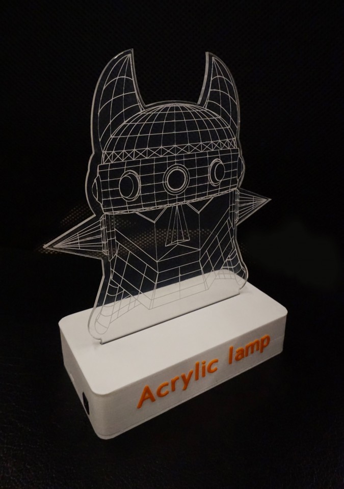
이번에 만든 프로젝트는 오래 전부터 제가 눈독을 들여왔던 아크릴 램프입니다.
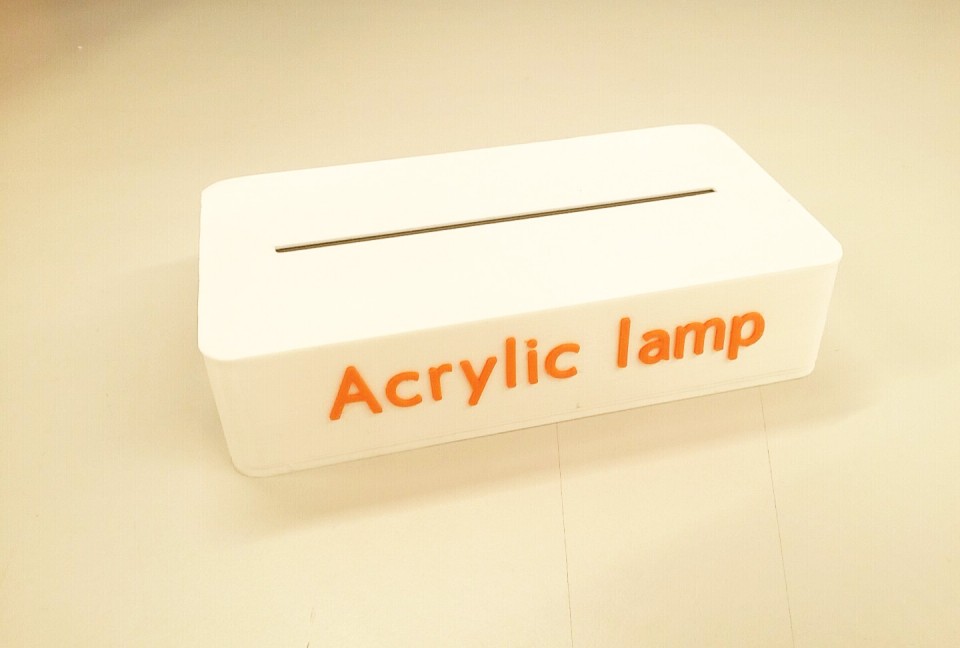
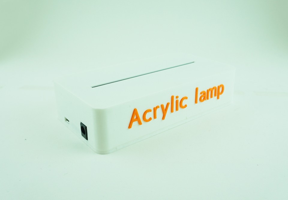
시중에서 판매하는 아크릴 램프의 모습은 아래와 같습니다.

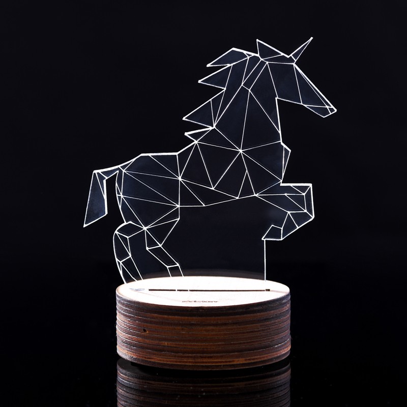


어떠신가요?
선으로 표현되는 모습이 참 아름답지 않나요?
봄을 맞이해 칙칙한 방의 분위기를 바꾸기 위해 구입을 해서 사용하려고 했으나..... 그렇다면 메이커가 아니겠죠?
자신이 필요한 것을 직접 만들어보고, 나누는 것이 메이커 정신!
제가 가지고 있는 부품들을 활용해 쉽게 만들어 볼 수 있을 것 같다는 생각이 들어 바로 생각을 실천으로 옮겼습니다.
비교적 간단한 부품과 저렴한 가격으로 만들어 볼 수 있었습니다! ;)
자 그럼 프로젝트에 대해 살펴볼까요? GO~ GO~
개요

이번에 만들어 본 프로젝트는 'DIY 아크릴 램프'입니다.
유니크하고 신선한 디자인으로 자신의 방을 꾸며볼 수 있겠죠?
아크릴 램프의 원리는 아래와 같습니다.
- 스마트폰 어플리케이션(Color wheel)에서 색상을 선택하고, 선택한 색상에 대한 RGB 값을 오렌지보드 BLE로 전송합니다.
- 스마트폰으로부터 전송 받은 RGB 값으로 LED를 점등한다.
하드웨어의 동작 원리는 참 간단하죠? ;)
그렇다면 빛이 어떻게 선(line)적으로 표현이 가능한 걸까요?
아크릴의 경우 투명하기 때문에 LED의 빛이 아크릴을 타고 올라가게 됩니다.
여기서 아크릴에 스크래치(scratch)를 내주게 되면, 스크래치를 낸 부분에 홈이 생기게 되고, 그 홈에 LED의 빛이 머물게 되는 것 입니다.
즉 아크릴에 원하는 문양이나, 그림으로 스크래치를 내주게 되면, 스크래치를 내 준 부분만 LED의 빛이 머물러 선(line)적으로 표현이 되는 것이죠! ;)
원리를 알아봤으니 제작 과정을 살펴볼까요?
관련 튜토리얼
이 프로젝트에서는 오렌지보드 BLE, neopixel strip LED를 사용합니다.
코코아팹 컨텐츠를 참고해 미리 사용법을 익혀주세요!
* 제작을 진행하시기전 아래 링크를 통해 각 모듈의 라이브러리 다운로드와 함수 사용법을 인지하시는 것을 권장드립니다.
- 아두이노 안드로이드 블루투스 통신 기초 / 무드 램프 만들기 :
이번 프로젝트에서는 오렌지보드 BLE 튜토리얼인 "아두이노 안드로이드 블루투스 통신 기초 / 무드 램프 만들기" 에서 사용한 어플리케이션을 사용합니다.
아래 링크를 통해 어플리케이션 설치 파일(apk)을 다운로드 받으세요! ;)
- kocoafab-smartlight.apk 다운로드 / 다운로드2
앗! neopixel LED가 없으면 만들 수 없냐구요?
아닙니다! neopixel LED가 없으신 분들도 4~5개의 RGB LED를 연결해 사용해주시면 됩니다.
RGB LED를 이용해 만들고자 하시는 분은 아래 링크를 참고해주시면 됩니다. 사용하는 어플리케이션은 동일합니다! ;)
- 아두이노 안드로이드 블루투스 통신 기초 / RGB LED 제어하기
부품 목록
아크릴 램프에 사용되는 부품의 목록은 아래와 같습니다.
| NO | 부품명 | 수량 | 상세 설명 |
| 1 | 오렌지보드 BLE | 1 | Bluetooth 4.0 |
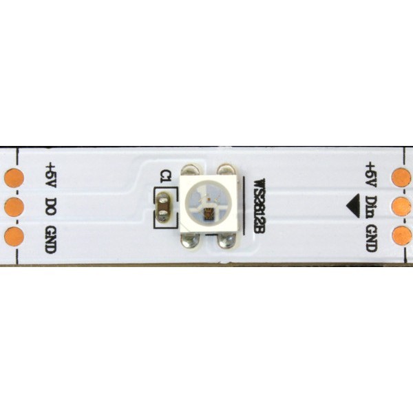
| 2 | Neopixel strip LED | 5~6 | |
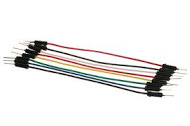
| 3 | 점퍼 케이블 | 3 |
| 부품명 | 오렌지보드 BLE | neopixel LED | 점퍼 케이블 |
| 파트 | 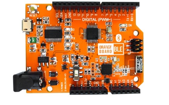 |
 |
 |
위에서 언급한 바와 같이 neopixel LED는 RGB LED로 대체가 가능합니다! ;)
하드웨어 메이킹
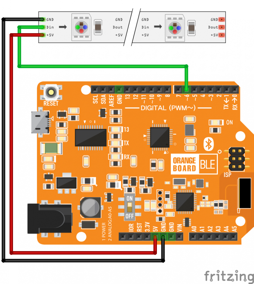
브레드보드 레이아웃
아래 보이는 레이아웃에서 오렌지보드는 오렌지보드 BLE로 이해해주시면 됩니다!
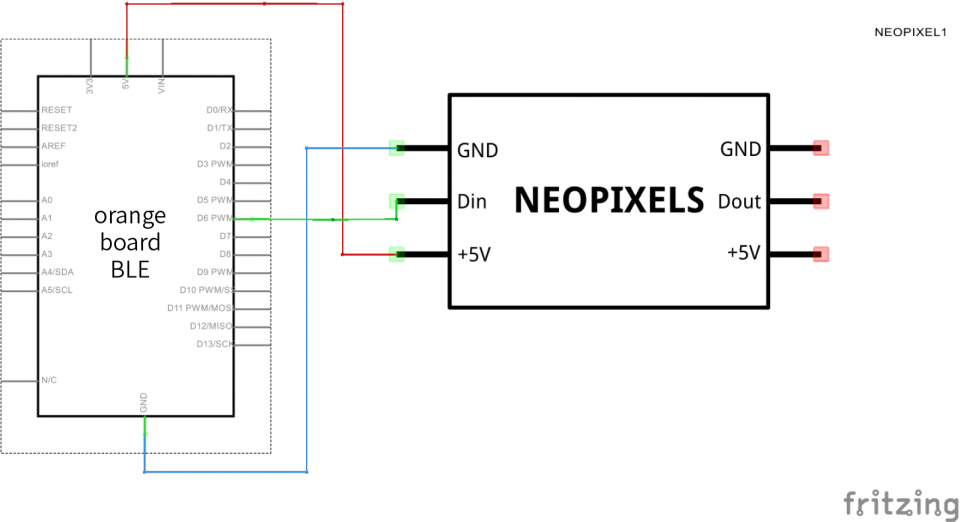
회로도(스케메틱)
소프트웨어 코딩
오렌지보드 BLE에 업로드 되는 코드입니다.
/*
제목 : DIY 아크릴 램프 만들기
내용 : 오렌지보드 BLE를 이용해 스마트폰으로 색상 제어가 가능한 나만의 아크릴 램프 만들기

이 소스코드는 kocoafab에서 작성하였습니다.
소스코드 배포시에는 출처를 남겨주시기 바랍니다.

E mail : contact@kocoa.or.kr
*/

#include <Adafruit_NeoPixel.h>
#include <SoftwareSerial.h>
#define PIN 6

// 오렌지 BLE보드는 4, 5번 핀에 BLE칩이 연결되어 있습니다.
SoftwareSerial BTSerial(4, 5);

// 각 색깔별로 기본값 0을 지정해 줍니다.
int redTemp = 0;
int blueTemp = 0;
int greenTemp = 0;

// 네오픽셀 LED 셋팅(여기선 12개의 Pixel을 사용했는데 연결한 Pixel 수에 맞게 숫자를 바꿔주세요)
Adafruit_NeoPixel strip = Adafruit_NeoPixel(12, PIN, NEO_GRB + NEO_KHZ800);

// Neopixel의 색깔을 정해주는 함수
void colorWipe(uint32_t c, uint8_t wait) {
  for (uint16_t i = 0 ; i<strip.numPixels() ; i++) {
    strip.setPixelColor(i, c);
    strip.show();
    delay(wait);
  }
}

void setup() {
  strip.begin();
  // 모든 LED Pixel을 Off로 셋팅해줍니다.
  strip.show();
  Serial.begin(9600);
  BTSerial.begin(9600);
}

void loop() {

  // 블루투스를 통해 데이터가 들어오면
  if (BTSerial.available()) {

    // 받은 데이터를 각 색깔별로 맞게 셋팅해줍니다.
    if (BTSerial.find("R")) {
      redTemp = BTSerial.parseInt();
    }
    if (BTSerial.find("G")) {
      greenTemp = BTSerial.parseInt();
    }
    if (BTSerial.find("B")) {
      blueTemp = BTSerial.parseInt();
    }

    // 각 색깔별로 제대로 된 수치가 들어왔는지 시리얼모니터로 확인
    Serial.print("R : ");
    Serial.println(redTemp);
    Serial.print("G : ");
    Serial.println(greenTemp);
    Serial.print("B : ");
    Serial.println(blueTemp);

    // 각 색깔별로 셋팅된 값을 이용하여 NeoPixel LED의 색깔을 밝혀줍니다.
    colorWipe(strip.Color(redTemp, greenTemp, blueTemp), 50);

    // NeoPixel LED 색깔이 모두 켜졌으면 각 색깔값들을 초기화 해줍니다.
    if (BTSerial.read() == 13) {
      redTemp = 0;
      greenTemp = 0;
      blueTemp = 0;
      Serial.println("Reset");
    }
  }
}
[Adafruit_NeoPixel.cpp]
/*-------------------------------------------------------------------------
Arduino library to control a wide variety of WS2811- and WS2812-based RGB
LED devices such as Adafruit FLORA RGB Smart Pixels and NeoPixel strips.
Currently handles 400 and 800 KHz bitstreams on 8, 12 and 16 MHz ATmega
MCUs, with LEDs wired for RGB or GRB color order. 8 MHz MCUs provide
output on PORTB and PORTD, while 16 MHz chips can handle most output pins
(possible exception with upper PORT registers on the Arduino Mega).
Written by Phil Burgess / Paint Your Dragon for Adafruit Industries,
contributions by PJRC and other members of the open source community.
Adafruit invests time and resources providing this open source code,
please support Adafruit and open-source hardware by purchasing products
from Adafruit!
-------------------------------------------------------------------------
This file is part of the Adafruit NeoPixel library.
NeoPixel is free software: you can redistribute it and/or modify
it under the terms of the GNU Lesser General Public License as
published by the Free Software Foundation, either version 3 of
the License, or (at your option) any later version.
NeoPixel is distributed in the hope that it will be useful,
but WITHOUT ANY WARRANTY; without even the implied warranty of
MERCHANTABILITY or FITNESS FOR A PARTICULAR PURPOSE. See the
GNU Lesser General Public License for more details.
You should have received a copy of the GNU Lesser General Public
License along with NeoPixel. If not, see
<http://www.gnu.org/licenses/>.
-------------------------------------------------------------------------*/
#include "Adafruit_NeoPixel.h"
Adafruit_NeoPixel::Adafruit_NeoPixel(uint16_t n, uint8_t p, uint8_t t) :
numLEDs(n), numBytes(n * 3), pin(p), brightness(0),
pixels(NULL), type(t), endTime(0)
#ifdef __AVR__
,port(portOutputRegister(digitalPinToPort(p))),
pinMask(digitalPinToBitMask(p))
#endif
{
if((pixels = (uint8_t *)malloc(numBytes))) {
memset(pixels, 0, numBytes);
}
if(t & NEO_GRB) { // GRB vs RGB; might add others if needed
rOffset = 1;
gOffset = 0;
bOffset = 2;
} else if (t & NEO_BRG) {
rOffset = 1;
gOffset = 2;
bOffset = 0;
} else {
rOffset = 0;
gOffset = 1;
bOffset = 2;
}
}
Adafruit_NeoPixel::~Adafruit_NeoPixel() {
if(pixels) free(pixels);
pinMode(pin, INPUT);
}
void Adafruit_NeoPixel::begin(void) {
pinMode(pin, OUTPUT);
digitalWrite(pin, LOW);
}
void Adafruit_NeoPixel::show(void) {
if(!pixels) return;
// Data latch = 50+ microsecond pause in the output stream. Rather than
// put a delay at the end of the function, the ending time is noted and
// the function will simply hold off (if needed) on issuing the
// subsequent round of data until the latch time has elapsed. This
// allows the mainline code to start generating the next frame of data
// rather than stalling for the latch.
while(!canShow());
// endTime is a private member (rather than global var) so that mutliple
// instances on different pins can be quickly issued in succession (each
// instance doesn't delay the next).
// In order to make this code runtime-configurable to work with any pin,
// SBI/CBI instructions are eschewed in favor of full PORT writes via the
// OUT or ST instructions. It relies on two facts: that peripheral
// functions (such as PWM) take precedence on output pins, so our PORT-
// wide writes won't interfere, and that interrupts are globally disabled
// while data is being issued to the LEDs, so no other code will be
// accessing the PORT. The code takes an initial 'snapshot' of the PORT
// state, computes 'pin high' and 'pin low' values, and writes these back
// to the PORT register as needed.
noInterrupts(); // Need 100% focus on instruction timing
#ifdef __AVR__
volatile uint16_t
i = numBytes; // Loop counter
volatile uint8_t
*ptr = pixels, // Pointer to next byte
b = *ptr++, // Current byte value
hi, // PORT w/output bit set high
lo; // PORT w/output bit set low
// Hand-tuned assembly code issues data to the LED drivers at a specific
// rate. There's separate code for different CPU speeds (8, 12, 16 MHz)
// for both the WS2811 (400 KHz) and WS2812 (800 KHz) drivers. The
// datastream timing for the LED drivers allows a little wiggle room each
// way (listed in the datasheets), so the conditions for compiling each
// case are set up for a range of frequencies rather than just the exact
// 8, 12 or 16 MHz values, permitting use with some close-but-not-spot-on
// devices (e.g. 16.5 MHz DigiSpark). The ranges were arrived at based
// on the datasheet figures and have not been extensively tested outside
// the canonical 8/12/16 MHz speeds; there's no guarantee these will work
// close to the extremes (or possibly they could be pushed further).
// Keep in mind only one CPU speed case actually gets compiled; the
// resulting program isn't as massive as it might look from source here.
// 8 MHz(ish) AVR ---------------------------------------------------------
#if (F_CPU >= 7400000UL) && (F_CPU <= 9500000UL)
#ifdef NEO_KHZ400
if((type & NEO_SPDMASK) == NEO_KHZ800) { // 800 KHz bitstream
#endif
volatile uint8_t n1, n2 = 0; // First, next bits out
// Squeezing an 800 KHz stream out of an 8 MHz chip requires code
// specific to each PORT register. At present this is only written
// to work with pins on PORTD or PORTB, the most likely use case --
// this covers all the pins on the Adafruit Flora and the bulk of
// digital pins on the Arduino Pro 8 MHz (keep in mind, this code
// doesn't even get compiled for 16 MHz boards like the Uno, Mega,
// Leonardo, etc., so don't bother extending this out of hand).
// Additional PORTs could be added if you really need them, just
// duplicate the else and loop and change the PORT. Each add'l
// PORT will require about 150(ish) bytes of program space.
// 10 instruction clocks per bit: HHxxxxxLLL
// OUT instructions: ^ ^ ^ (T=0,2,7)
#ifdef PORTD // PORTD isn't present on ATtiny85, etc.
if(port == &PORTD) {
hi = PORTD | pinMask;
lo = PORTD & ~pinMask;
n1 = lo;
if(b & 0x80) n1 = hi;
// Dirty trick: RJMPs proceeding to the next instruction are used
// to delay two clock cycles in one instruction word (rather than
// using two NOPs). This was necessary in order to squeeze the
// loop down to exactly 64 words -- the maximum possible for a
// relative branch.
asm volatile(
"headD:" "\n\t" // Clk Pseudocode
// Bit 7:
"out %[port] , %[hi]" "\n\t" // 1 PORT = hi
"mov %[n2] , %[lo]" "\n\t" // 1 n2 = lo
"out %[port] , %[n1]" "\n\t" // 1 PORT = n1
"rjmp .+0" "\n\t" // 2 nop nop
"sbrc %[byte] , 6" "\n\t" // 1-2 if(b & 0x40)
"mov %[n2] , %[hi]" "\n\t" // 0-1 n2 = hi
"out %[port] , %[lo]" "\n\t" // 1 PORT = lo
"rjmp .+0" "\n\t" // 2 nop nop
// Bit 6:
"out %[port] , %[hi]" "\n\t" // 1 PORT = hi
"mov %[n1] , %[lo]" "\n\t" // 1 n1 = lo
"out %[port] , %[n2]" "\n\t" // 1 PORT = n2
"rjmp .+0" "\n\t" // 2 nop nop
"sbrc %[byte] , 5" "\n\t" // 1-2 if(b & 0x20)
"mov %[n1] , %[hi]" "\n\t" // 0-1 n1 = hi
"out %[port] , %[lo]" "\n\t" // 1 PORT = lo
"rjmp .+0" "\n\t" // 2 nop nop
// Bit 5:
"out %[port] , %[hi]" "\n\t" // 1 PORT = hi
"mov %[n2] , %[lo]" "\n\t" // 1 n2 = lo
"out %[port] , %[n1]" "\n\t" // 1 PORT = n1
"rjmp .+0" "\n\t" // 2 nop nop
"sbrc %[byte] , 4" "\n\t" // 1-2 if(b & 0x10)
"mov %[n2] , %[hi]" "\n\t" // 0-1 n2 = hi
"out %[port] , %[lo]" "\n\t" // 1 PORT = lo
"rjmp .+0" "\n\t" // 2 nop nop
// Bit 4:
"out %[port] , %[hi]" "\n\t" // 1 PORT = hi
"mov %[n1] , %[lo]" "\n\t" // 1 n1 = lo
"out %[port] , %[n2]" "\n\t" // 1 PORT = n2
"rjmp .+0" "\n\t" // 2 nop nop
"sbrc %[byte] , 3" "\n\t" // 1-2 if(b & 0x08)
"mov %[n1] , %[hi]" "\n\t" // 0-1 n1 = hi
"out %[port] , %[lo]" "\n\t" // 1 PORT = lo
"rjmp .+0" "\n\t" // 2 nop nop
// Bit 3:
"out %[port] , %[hi]" "\n\t" // 1 PORT = hi
"mov %[n2] , %[lo]" "\n\t" // 1 n2 = lo
"out %[port] , %[n1]" "\n\t" // 1 PORT = n1
"rjmp .+0" "\n\t" // 2 nop nop
"sbrc %[byte] , 2" "\n\t" // 1-2 if(b & 0x04)
"mov %[n2] , %[hi]" "\n\t" // 0-1 n2 = hi
"out %[port] , %[lo]" "\n\t" // 1 PORT = lo
"rjmp .+0" "\n\t" // 2 nop nop
// Bit 2:
"out %[port] , %[hi]" "\n\t" // 1 PORT = hi
"mov %[n1] , %[lo]" "\n\t" // 1 n1 = lo
"out %[port] , %[n2]" "\n\t" // 1 PORT = n2
"rjmp .+0" "\n\t" // 2 nop nop
"sbrc %[byte] , 1" "\n\t" // 1-2 if(b & 0x02)
"mov %[n1] , %[hi]" "\n\t" // 0-1 n1 = hi
"out %[port] , %[lo]" "\n\t" // 1 PORT = lo
"rjmp .+0" "\n\t" // 2 nop nop
// Bit 1:
"out %[port] , %[hi]" "\n\t" // 1 PORT = hi
"mov %[n2] , %[lo]" "\n\t" // 1 n2 = lo
"out %[port] , %[n1]" "\n\t" // 1 PORT = n1
"rjmp .+0" "\n\t" // 2 nop nop
"sbrc %[byte] , 0" "\n\t" // 1-2 if(b & 0x01)
"mov %[n2] , %[hi]" "\n\t" // 0-1 n2 = hi
"out %[port] , %[lo]" "\n\t" // 1 PORT = lo
"sbiw %[count], 1" "\n\t" // 2 i-- (don't act on Z flag yet)
// Bit 0:
"out %[port] , %[hi]" "\n\t" // 1 PORT = hi
"mov %[n1] , %[lo]" "\n\t" // 1 n1 = lo
"out %[port] , %[n2]" "\n\t" // 1 PORT = n2
"ld %[byte] , %a[ptr]+" "\n\t" // 2 b = *ptr++
"sbrc %[byte] , 7" "\n\t" // 1-2 if(b & 0x80)
"mov %[n1] , %[hi]" "\n\t" // 0-1 n1 = hi
"out %[port] , %[lo]" "\n\t" // 1 PORT = lo
"brne headD" "\n" // 2 while(i) (Z flag set above)
: [byte] "+r" (b),
[n1] "+r" (n1),
[n2] "+r" (n2),
[count] "+w" (i)
: [port] "I" (_SFR_IO_ADDR(PORTD)),
[ptr] "e" (ptr),
[hi] "r" (hi),
[lo] "r" (lo));
} else if(port == &PORTB) {
#endif // PORTD
// Same as above, just switched to PORTB and stripped of comments.
hi = PORTB | pinMask;
lo = PORTB & ~pinMask;
n1 = lo;
if(b & 0x80) n1 = hi;
asm volatile(
"headB:" "\n\t"
"out %[port] , %[hi]" "\n\t"
"mov %[n2] , %[lo]" "\n\t"
"out %[port] , %[n1]" "\n\t"
"rjmp .+0" "\n\t"
"sbrc %[byte] , 6" "\n\t"
"mov %[n2] , %[hi]" "\n\t"
"out %[port] , %[lo]" "\n\t"
"rjmp .+0" "\n\t"
"out %[port] , %[hi]" "\n\t"
"mov %[n1] , %[lo]" "\n\t"
"out %[port] , %[n2]" "\n\t"
"rjmp .+0" "\n\t"
"sbrc %[byte] , 5" "\n\t"
"mov %[n1] , %[hi]" "\n\t"
"out %[port] , %[lo]" "\n\t"
"rjmp .+0" "\n\t"
"out %[port] , %[hi]" "\n\t"
"mov %[n2] , %[lo]" "\n\t"
"out %[port] , %[n1]" "\n\t"
"rjmp .+0" "\n\t"
"sbrc %[byte] , 4" "\n\t"
"mov %[n2] , %[hi]" "\n\t"
"out %[port] , %[lo]" "\n\t"
"rjmp .+0" "\n\t"
"out %[port] , %[hi]" "\n\t"
"mov %[n1] , %[lo]" "\n\t"
"out %[port] , %[n2]" "\n\t"
"rjmp .+0" "\n\t"
"sbrc %[byte] , 3" "\n\t"
"mov %[n1] , %[hi]" "\n\t"
"out %[port] , %[lo]" "\n\t"
"rjmp .+0" "\n\t"
"out %[port] , %[hi]" "\n\t"
"mov %[n2] , %[lo]" "\n\t"
"out %[port] , %[n1]" "\n\t"
"rjmp .+0" "\n\t"
"sbrc %[byte] , 2" "\n\t"
"mov %[n2] , %[hi]" "\n\t"
"out %[port] , %[lo]" "\n\t"
"rjmp .+0" "\n\t"
"out %[port] , %[hi]" "\n\t"
"mov %[n1] , %[lo]" "\n\t"
"out %[port] , %[n2]" "\n\t"
"rjmp .+0" "\n\t"
"sbrc %[byte] , 1" "\n\t"
"mov %[n1] , %[hi]" "\n\t"
"out %[port] , %[lo]" "\n\t"
"rjmp .+0" "\n\t"
"out %[port] , %[hi]" "\n\t"
"mov %[n2] , %[lo]" "\n\t"
"out %[port] , %[n1]" "\n\t"
"rjmp .+0" "\n\t"
"sbrc %[byte] , 0" "\n\t"
"mov %[n2] , %[hi]" "\n\t"
"out %[port] , %[lo]" "\n\t"
"sbiw %[count], 1" "\n\t"
"out %[port] , %[hi]" "\n\t"
"mov %[n1] , %[lo]" "\n\t"
"out %[port] , %[n2]" "\n\t"
"ld %[byte] , %a[ptr]+" "\n\t"
"sbrc %[byte] , 7" "\n\t"
"mov %[n1] , %[hi]" "\n\t"
"out %[port] , %[lo]" "\n\t"
"brne headB" "\n"
: [byte] "+r" (b), [n1] "+r" (n1), [n2] "+r" (n2), [count] "+w" (i)
: [port] "I" (_SFR_IO_ADDR(PORTB)), [ptr] "e" (ptr), [hi] "r" (hi),
[lo] "r" (lo));
#ifdef PORTD
} // endif PORTB
#endif
#ifdef NEO_KHZ400
} else { // end 800 KHz, do 400 KHz
// Timing is more relaxed; unrolling the inner loop for each bit is
// not necessary. Still using the peculiar RJMPs as 2X NOPs, not out
// of need but just to trim the code size down a little.
// This 400-KHz-datastream-on-8-MHz-CPU code is not quite identical
// to the 800-on-16 code later -- the hi/lo timing between WS2811 and
// WS2812 is not simply a 2:1 scale!
// 20 inst. clocks per bit: HHHHxxxxxxLLLLLLLLLL
// ST instructions: ^ ^ ^ (T=0,4,10)
volatile uint8_t next, bit;
hi = *port | pinMask;
lo = *port & ~pinMask;
next = lo;
bit = 8;
asm volatile(
"head20:" "\n\t" // Clk Pseudocode (T = 0)
"st %a[port], %[hi]" "\n\t" // 2 PORT = hi (T = 2)
"sbrc %[byte] , 7" "\n\t" // 1-2 if(b & 128)
"mov %[next], %[hi]" "\n\t" // 0-1 next = hi (T = 4)
"st %a[port], %[next]" "\n\t" // 2 PORT = next (T = 6)
"mov %[next] , %[lo]" "\n\t" // 1 next = lo (T = 7)
"dec %[bit]" "\n\t" // 1 bit-- (T = 8)
"breq nextbyte20" "\n\t" // 1-2 if(bit == 0)
"rol %[byte]" "\n\t" // 1 b <<= 1 (T = 10)
"st %a[port], %[lo]" "\n\t" // 2 PORT = lo (T = 12)
"rjmp .+0" "\n\t" // 2 nop nop (T = 14)
"rjmp .+0" "\n\t" // 2 nop nop (T = 16)
"rjmp .+0" "\n\t" // 2 nop nop (T = 18)
"rjmp head20" "\n\t" // 2 -> head20 (next bit out)
"nextbyte20:" "\n\t" // (T = 10)
"st %a[port], %[lo]" "\n\t" // 2 PORT = lo (T = 12)
"nop" "\n\t" // 1 nop (T = 13)
"ldi %[bit] , 8" "\n\t" // 1 bit = 8 (T = 14)
"ld %[byte] , %a[ptr]+" "\n\t" // 2 b = *ptr++ (T = 16)
"sbiw %[count], 1" "\n\t" // 2 i-- (T = 18)
"brne head20" "\n" // 2 if(i != 0) -> (next byte)
: [port] "+e" (port),
[byte] "+r" (b),
[bit] "+r" (bit),
[next] "+r" (next),
[count] "+w" (i)
: [hi] "r" (hi),
[lo] "r" (lo),
[ptr] "e" (ptr));
}
#endif
// 12 MHz(ish) AVR --------------------------------------------------------
#elif (F_CPU >= 11100000UL) && (F_CPU <= 14300000UL)
#ifdef NEO_KHZ400
if((type & NEO_SPDMASK) == NEO_KHZ800) { // 800 KHz bitstream
#endif
// In the 12 MHz case, an optimized 800 KHz datastream (no dead time
// between bytes) requires a PORT-specific loop similar to the 8 MHz
// code (but a little more relaxed in this case).
// 15 instruction clocks per bit: HHHHxxxxxxLLLLL
// OUT instructions: ^ ^ ^ (T=0,4,10)
volatile uint8_t next;
#ifdef PORTD
if(port == &PORTD) {
hi = PORTD | pinMask;
lo = PORTD & ~pinMask;
next = lo;
if(b & 0x80) next = hi;
// Don't "optimize" the OUT calls into the bitTime subroutine;
// we're exploiting the RCALL and RET as 3- and 4-cycle NOPs!
asm volatile(
"headD:" "\n\t" // (T = 0)
"out %[port], %[hi]" "\n\t" // (T = 1)
"rcall bitTimeD" "\n\t" // Bit 7 (T = 15)
"out %[port], %[hi]" "\n\t"
"rcall bitTimeD" "\n\t" // Bit 6
"out %[port], %[hi]" "\n\t"
"rcall bitTimeD" "\n\t" // Bit 5
"out %[port], %[hi]" "\n\t"
"rcall bitTimeD" "\n\t" // Bit 4
"out %[port], %[hi]" "\n\t"
"rcall bitTimeD" "\n\t" // Bit 3
"out %[port], %[hi]" "\n\t"
"rcall bitTimeD" "\n\t" // Bit 2
"out %[port], %[hi]" "\n\t"
"rcall bitTimeD" "\n\t" // Bit 1
// Bit 0:
"out %[port] , %[hi]" "\n\t" // 1 PORT = hi (T = 1)
"rjmp .+0" "\n\t" // 2 nop nop (T = 3)
"ld %[byte] , %a[ptr]+" "\n\t" // 2 b = *ptr++ (T = 5)
"out %[port] , %[next]" "\n\t" // 1 PORT = next (T = 6)
"mov %[next] , %[lo]" "\n\t" // 1 next = lo (T = 7)
"sbrc %[byte] , 7" "\n\t" // 1-2 if(b & 0x80) (T = 8)
"mov %[next] , %[hi]" "\n\t" // 0-1 next = hi (T = 9)
"nop" "\n\t" // 1 (T = 10)
"out %[port] , %[lo]" "\n\t" // 1 PORT = lo (T = 11)
"sbiw %[count], 1" "\n\t" // 2 i-- (T = 13)
"brne headD" "\n\t" // 2 if(i != 0) -> (next byte)
"rjmp doneD" "\n\t"
"bitTimeD:" "\n\t" // nop nop nop (T = 4)
"out %[port], %[next]" "\n\t" // 1 PORT = next (T = 5)
"mov %[next], %[lo]" "\n\t" // 1 next = lo (T = 6)
"rol %[byte]" "\n\t" // 1 b <<= 1 (T = 7)
"sbrc %[byte], 7" "\n\t" // 1-2 if(b & 0x80) (T = 8)
"mov %[next], %[hi]" "\n\t" // 0-1 next = hi (T = 9)
"nop" "\n\t" // 1 (T = 10)
"out %[port], %[lo]" "\n\t" // 1 PORT = lo (T = 11)
"ret" "\n\t" // 4 nop nop nop nop (T = 15)
"doneD:" "\n"
: [byte] "+r" (b),
[next] "+r" (next),
[count] "+w" (i)
: [port] "I" (_SFR_IO_ADDR(PORTD)),
[ptr] "e" (ptr),
[hi] "r" (hi),
[lo] "r" (lo));
} else if(port == &PORTB) {
#endif // PORTD
hi = PORTB | pinMask;
lo = PORTB & ~pinMask;
next = lo;
if(b & 0x80) next = hi;
// Same as above, just set for PORTB & stripped of comments
asm volatile(
"headB:" "\n\t"
"out %[port], %[hi]" "\n\t"
"rcall bitTimeB" "\n\t"
"out %[port], %[hi]" "\n\t"
"rcall bitTimeB" "\n\t"
"out %[port], %[hi]" "\n\t"
"rcall bitTimeB" "\n\t"
"out %[port], %[hi]" "\n\t"
"rcall bitTimeB" "\n\t"
"out %[port], %[hi]" "\n\t"
"rcall bitTimeB" "\n\t"
"out %[port], %[hi]" "\n\t"
"rcall bitTimeB" "\n\t"
"out %[port], %[hi]" "\n\t"
"rcall bitTimeB" "\n\t"
"out %[port] , %[hi]" "\n\t"
"rjmp .+0" "\n\t"
"ld %[byte] , %a[ptr]+" "\n\t"
"out %[port] , %[next]" "\n\t"
"mov %[next] , %[lo]" "\n\t"
"sbrc %[byte] , 7" "\n\t"
"mov %[next] , %[hi]" "\n\t"
"nop" "\n\t"
"out %[port] , %[lo]" "\n\t"
"sbiw %[count], 1" "\n\t"
"brne headB" "\n\t"
"rjmp doneB" "\n\t"
"bitTimeB:" "\n\t"
"out %[port], %[next]" "\n\t"
"mov %[next], %[lo]" "\n\t"
"rol %[byte]" "\n\t"
"sbrc %[byte], 7" "\n\t"
"mov %[next], %[hi]" "\n\t"
"nop" "\n\t"
"out %[port], %[lo]" "\n\t"
"ret" "\n\t"
"doneB:" "\n"
: [byte] "+r" (b), [next] "+r" (next), [count] "+w" (i)
: [port] "I" (_SFR_IO_ADDR(PORTB)), [ptr] "e" (ptr), [hi] "r" (hi),
[lo] "r" (lo));
#ifdef PORTD
}
#endif
#ifdef NEO_KHZ400
} else { // 400 KHz
// 30 instruction clocks per bit: HHHHHHxxxxxxxxxLLLLLLLLLLLLLLL
// ST instructions: ^ ^ ^ (T=0,6,15)
volatile uint8_t next, bit;
hi = *port | pinMask;
lo = *port & ~pinMask;
next = lo;
bit = 8;
asm volatile(
"head30:" "\n\t" // Clk Pseudocode (T = 0)
"st %a[port], %[hi]" "\n\t" // 2 PORT = hi (T = 2)
"sbrc %[byte] , 7" "\n\t" // 1-2 if(b & 128)
"mov %[next], %[hi]" "\n\t" // 0-1 next = hi (T = 4)
"rjmp .+0" "\n\t" // 2 nop nop (T = 6)
"st %a[port], %[next]" "\n\t" // 2 PORT = next (T = 8)
"rjmp .+0" "\n\t" // 2 nop nop (T = 10)
"rjmp .+0" "\n\t" // 2 nop nop (T = 12)
"rjmp .+0" "\n\t" // 2 nop nop (T = 14)
"nop" "\n\t" // 1 nop (T = 15)
"st %a[port], %[lo]" "\n\t" // 2 PORT = lo (T = 17)
"rjmp .+0" "\n\t" // 2 nop nop (T = 19)
"dec %[bit]" "\n\t" // 1 bit-- (T = 20)
"breq nextbyte30" "\n\t" // 1-2 if(bit == 0)
"rol %[byte]" "\n\t" // 1 b <<= 1 (T = 22)
"rjmp .+0" "\n\t" // 2 nop nop (T = 24)
"rjmp .+0" "\n\t" // 2 nop nop (T = 26)
"rjmp .+0" "\n\t" // 2 nop nop (T = 28)
"rjmp head30" "\n\t" // 2 -> head30 (next bit out)
"nextbyte30:" "\n\t" // (T = 22)
"nop" "\n\t" // 1 nop (T = 23)
"ldi %[bit] , 8" "\n\t" // 1 bit = 8 (T = 24)
"ld %[byte] , %a[ptr]+" "\n\t" // 2 b = *ptr++ (T = 26)
"sbiw %[count], 1" "\n\t" // 2 i-- (T = 28)
"brne head30" "\n" // 1-2 if(i != 0) -> (next byte)
: [port] "+e" (port),
[byte] "+r" (b),
[bit] "+r" (bit),
[next] "+r" (next),
[count] "+w" (i)
: [hi] "r" (hi),
[lo] "r" (lo),
[ptr] "e" (ptr));
}
#endif
// 16 MHz(ish) AVR --------------------------------------------------------
#elif (F_CPU >= 15400000UL) && (F_CPU <= 19000000L)
#ifdef NEO_KHZ400
if((type & NEO_SPDMASK) == NEO_KHZ800) { // 800 KHz bitstream
#endif
// WS2811 and WS2812 have different hi/lo duty cycles; this is
// similar but NOT an exact copy of the prior 400-on-8 code.
// 20 inst. clocks per bit: HHHHHxxxxxxxxLLLLLLL
// ST instructions: ^ ^ ^ (T=0,5,13)
volatile uint8_t next, bit;
hi = *port | pinMask;
lo = *port & ~pinMask;
next = lo;
bit = 8;
asm volatile(
"head20:" "\n\t" // Clk Pseudocode (T = 0)
"st %a[port], %[hi]" "\n\t" // 2 PORT = hi (T = 2)
"sbrc %[byte], 7" "\n\t" // 1-2 if(b & 128)
"mov %[next], %[hi]" "\n\t" // 0-1 next = hi (T = 4)
"dec %[bit]" "\n\t" // 1 bit-- (T = 5)
"st %a[port], %[next]" "\n\t" // 2 PORT = next (T = 7)
"mov %[next] , %[lo]" "\n\t" // 1 next = lo (T = 8)
"breq nextbyte20" "\n\t" // 1-2 if(bit == 0) (from dec above)
"rol %[byte]" "\n\t" // 1 b <<= 1 (T = 10)
"rjmp .+0" "\n\t" // 2 nop nop (T = 12)
"nop" "\n\t" // 1 nop (T = 13)
"st %a[port], %[lo]" "\n\t" // 2 PORT = lo (T = 15)
"nop" "\n\t" // 1 nop (T = 16)
"rjmp .+0" "\n\t" // 2 nop nop (T = 18)
"rjmp head20" "\n\t" // 2 -> head20 (next bit out)
"nextbyte20:" "\n\t" // (T = 10)
"ldi %[bit] , 8" "\n\t" // 1 bit = 8 (T = 11)
"ld %[byte] , %a[ptr]+" "\n\t" // 2 b = *ptr++ (T = 13)
"st %a[port], %[lo]" "\n\t" // 2 PORT = lo (T = 15)
"nop" "\n\t" // 1 nop (T = 16)
"sbiw %[count], 1" "\n\t" // 2 i-- (T = 18)
"brne head20" "\n" // 2 if(i != 0) -> (next byte)
: [port] "+e" (port),
[byte] "+r" (b),
[bit] "+r" (bit),
[next] "+r" (next),
[count] "+w" (i)
: [ptr] "e" (ptr),
[hi] "r" (hi),
[lo] "r" (lo));
#ifdef NEO_KHZ400
} else { // 400 KHz
// The 400 KHz clock on 16 MHz MCU is the most 'relaxed' version.
// 40 inst. clocks per bit: HHHHHHHHxxxxxxxxxxxxLLLLLLLLLLLLLLLLLLLL
// ST instructions: ^ ^ ^ (T=0,8,20)
volatile uint8_t next, bit;
hi = *port | pinMask;
lo = *port & ~pinMask;
next = lo;
bit = 8;
asm volatile(
"head40:" "\n\t" // Clk Pseudocode (T = 0)
"st %a[port], %[hi]" "\n\t" // 2 PORT = hi (T = 2)
"sbrc %[byte] , 7" "\n\t" // 1-2 if(b & 128)
"mov %[next] , %[hi]" "\n\t" // 0-1 next = hi (T = 4)
"rjmp .+0" "\n\t" // 2 nop nop (T = 6)
"rjmp .+0" "\n\t" // 2 nop nop (T = 8)
"st %a[port], %[next]" "\n\t" // 2 PORT = next (T = 10)
"rjmp .+0" "\n\t" // 2 nop nop (T = 12)
"rjmp .+0" "\n\t" // 2 nop nop (T = 14)
"rjmp .+0" "\n\t" // 2 nop nop (T = 16)
"rjmp .+0" "\n\t" // 2 nop nop (T = 18)
"rjmp .+0" "\n\t" // 2 nop nop (T = 20)
"st %a[port], %[lo]" "\n\t" // 2 PORT = lo (T = 22)
"nop" "\n\t" // 1 nop (T = 23)
"mov %[next] , %[lo]" "\n\t" // 1 next = lo (T = 24)
"dec %[bit]" "\n\t" // 1 bit-- (T = 25)
"breq nextbyte40" "\n\t" // 1-2 if(bit == 0)
"rol %[byte]" "\n\t" // 1 b <<= 1 (T = 27)
"nop" "\n\t" // 1 nop (T = 28)
"rjmp .+0" "\n\t" // 2 nop nop (T = 30)
"rjmp .+0" "\n\t" // 2 nop nop (T = 32)
"rjmp .+0" "\n\t" // 2 nop nop (T = 34)
"rjmp .+0" "\n\t" // 2 nop nop (T = 36)
"rjmp .+0" "\n\t" // 2 nop nop (T = 38)
"rjmp head40" "\n\t" // 2 -> head40 (next bit out)
"nextbyte40:" "\n\t" // (T = 27)
"ldi %[bit] , 8" "\n\t" // 1 bit = 8 (T = 28)
"ld %[byte] , %a[ptr]+" "\n\t" // 2 b = *ptr++ (T = 30)
"rjmp .+0" "\n\t" // 2 nop nop (T = 32)
"st %a[port], %[lo]" "\n\t" // 2 PORT = lo (T = 34)
"rjmp .+0" "\n\t" // 2 nop nop (T = 36)
"sbiw %[count], 1" "\n\t" // 2 i-- (T = 38)
"brne head40" "\n" // 1-2 if(i != 0) -> (next byte)
: [port] "+e" (port),
[byte] "+r" (b),
[bit] "+r" (bit),
[next] "+r" (next),
[count] "+w" (i)
: [ptr] "e" (ptr),
[hi] "r" (hi),
[lo] "r" (lo));
}
#endif
#else
#error "CPU SPEED NOT SUPPORTED"
#endif
#elif defined(__arm__)
#if defined(__MK20DX128__) || defined(__MK20DX256__) // Teensy 3.0 & 3.1
#define CYCLES_800_T0H (F_CPU / 4000000)
#define CYCLES_800_T1H (F_CPU / 1250000)
#define CYCLES_800 (F_CPU / 800000)
#define CYCLES_400_T0H (F_CPU / 2000000)
#define CYCLES_400_T1H (F_CPU / 833333)
#define CYCLES_400 (F_CPU / 400000)
uint8_t *p = pixels,
*end = p + numBytes, pix, mask;
volatile uint8_t *set = portSetRegister(pin),
*clr = portClearRegister(pin);
uint32_t cyc;
ARM_DEMCR |= ARM_DEMCR_TRCENA;
ARM_DWT_CTRL |= ARM_DWT_CTRL_CYCCNTENA;
#ifdef NEO_KHZ400
if((type & NEO_SPDMASK) == NEO_KHZ800) { // 800 KHz bitstream
#endif
cyc = ARM_DWT_CYCCNT + CYCLES_800;
while(p < end) {
pix = *p++;
for(mask = 0x80; mask; mask >>= 1) {
while(ARM_DWT_CYCCNT - cyc < CYCLES_800);
cyc = ARM_DWT_CYCCNT;
*set = 1;
if(pix & mask) {
while(ARM_DWT_CYCCNT - cyc < CYCLES_800_T1H);
} else {
while(ARM_DWT_CYCCNT - cyc < CYCLES_800_T0H);
}
*clr = 1;
}
}
while(ARM_DWT_CYCCNT - cyc < CYCLES_800);
#ifdef NEO_KHZ400
} else { // 400 kHz bitstream
cyc = ARM_DWT_CYCCNT + CYCLES_400;
while(p < end) {
pix = *p++;
for(mask = 0x80; mask; mask >>= 1) {
while(ARM_DWT_CYCCNT - cyc < CYCLES_400);
cyc = ARM_DWT_CYCCNT;
*set = 1;
if(pix & mask) {
while(ARM_DWT_CYCCNT - cyc < CYCLES_400_T1H);
} else {
while(ARM_DWT_CYCCNT - cyc < CYCLES_400_T0H);
}
*clr = 1;
}
}
while(ARM_DWT_CYCCNT - cyc < CYCLES_400);
}
#endif
#elif defined(__MKL26Z64__) // Teensy-LC
#if F_CPU == 48000000
uint8_t *p = pixels,
pix, count, dly,
bitmask = digitalPinToBitMask(pin);
volatile uint8_t *reg = portSetRegister(pin);
uint32_t num = numBytes;
asm volatile(
"L%=_begin:" "\n\t"
"ldrb %[pix], [%[p], #0]" "\n\t"
"lsl %[pix], #24" "\n\t"
"movs %[count], #7" "\n\t"
"L%=_loop:" "\n\t"
"lsl %[pix], #1" "\n\t"
"bcs L%=_loop_one" "\n\t"
"L%=_loop_zero:"
"strb %[bitmask], [%[reg], #0]" "\n\t"
"movs %[dly], #4" "\n\t"
"L%=_loop_delay_T0H:" "\n\t"
"sub %[dly], #1" "\n\t"
"bne L%=_loop_delay_T0H" "\n\t"
"strb %[bitmask], [%[reg], #4]" "\n\t"
"movs %[dly], #13" "\n\t"
"L%=_loop_delay_T0L:" "\n\t"
"sub %[dly], #1" "\n\t"
"bne L%=_loop_delay_T0L" "\n\t"
"b L%=_next" "\n\t"
"L%=_loop_one:"
"strb %[bitmask], [%[reg], #0]" "\n\t"
"movs %[dly], #13" "\n\t"
"L%=_loop_delay_T1H:" "\n\t"
"sub %[dly], #1" "\n\t"
"bne L%=_loop_delay_T1H" "\n\t"
"strb %[bitmask], [%[reg], #4]" "\n\t"
"movs %[dly], #4" "\n\t"
"L%=_loop_delay_T1L:" "\n\t"
"sub %[dly], #1" "\n\t"
"bne L%=_loop_delay_T1L" "\n\t"
"nop" "\n\t"
"L%=_next:" "\n\t"
"sub %[count], #1" "\n\t"
"bne L%=_loop" "\n\t"
"lsl %[pix], #1" "\n\t"
"bcs L%=_last_one" "\n\t"
"L%=_last_zero:"
"strb %[bitmask], [%[reg], #0]" "\n\t"
"movs %[dly], #4" "\n\t"
"L%=_last_delay_T0H:" "\n\t"
"sub %[dly], #1" "\n\t"
"bne L%=_last_delay_T0H" "\n\t"
"strb %[bitmask], [%[reg], #4]" "\n\t"
"movs %[dly], #10" "\n\t"
"L%=_last_delay_T0L:" "\n\t"
"sub %[dly], #1" "\n\t"
"bne L%=_last_delay_T0L" "\n\t"
"b L%=_repeat" "\n\t"
"L%=_last_one:"
"strb %[bitmask], [%[reg], #0]" "\n\t"
"movs %[dly], #13" "\n\t"
"L%=_last_delay_T1H:" "\n\t"
"sub %[dly], #1" "\n\t"
"bne L%=_last_delay_T1H" "\n\t"
"strb %[bitmask], [%[reg], #4]" "\n\t"
"movs %[dly], #1" "\n\t"
"L%=_last_delay_T1L:" "\n\t"
"sub %[dly], #1" "\n\t"
"bne L%=_last_delay_T1L" "\n\t"
"nop" "\n\t"
"L%=_repeat:" "\n\t"
"add %[p], #1" "\n\t"
"sub %[num], #1" "\n\t"
"bne L%=_begin" "\n\t"
"L%=_done:" "\n\t"
: [p] "+r" (p),
[pix] "=&r" (pix),
[count] "=&r" (count),
[dly] "=&r" (dly),
[num] "+r" (num)
: [bitmask] "r" (bitmask),
[reg] "r" (reg)
);
#else
#error "Sorry, only 48 MHz is supported, please set Tools > CPU Speed to 48 MHz"
#endif
#else // Arduino Due
#define SCALE VARIANT_MCK / 2UL / 1000000UL
#define INST (2UL * F_CPU / VARIANT_MCK)
#define TIME_800_0 ((int)(0.40 * SCALE + 0.5) - (5 * INST))
#define TIME_800_1 ((int)(0.80 * SCALE + 0.5) - (5 * INST))
#define PERIOD_800 ((int)(1.25 * SCALE + 0.5) - (5 * INST))
#define TIME_400_0 ((int)(0.50 * SCALE + 0.5) - (5 * INST))
#define TIME_400_1 ((int)(1.20 * SCALE + 0.5) - (5 * INST))
#define PERIOD_400 ((int)(2.50 * SCALE + 0.5) - (5 * INST))
int pinMask, time0, time1, period, t;
Pio *port;
volatile WoReg *portSet, *portClear, *timeValue, *timeReset;
uint8_t *p, *end, pix, mask;
pmc_set_writeprotect(false);
pmc_enable_periph_clk((uint32_t)TC3_IRQn);
TC_Configure(TC1, 0,
TC_CMR_WAVE | TC_CMR_WAVSEL_UP | TC_CMR_TCCLKS_TIMER_CLOCK1);
TC_Start(TC1, 0);
pinMask = g_APinDescription[pin].ulPin; // Don't 'optimize' these into
port = g_APinDescription[pin].pPort; // declarations above. Want to
portSet = &(port->PIO_SODR); // burn a few cycles after
portClear = &(port->PIO_CODR); // starting timer to minimize
timeValue = &(TC1->TC_CHANNEL[0].TC_CV); // the initial 'while'.
timeReset = &(TC1->TC_CHANNEL[0].TC_CCR);
p = pixels;
end = p + numBytes;
pix = *p++;
mask = 0x80;
#ifdef NEO_KHZ400
if((type & NEO_SPDMASK) == NEO_KHZ800) { // 800 KHz bitstream
#endif
time0 = TIME_800_0;
time1 = TIME_800_1;
period = PERIOD_800;
#ifdef NEO_KHZ400
} else { // 400 KHz bitstream
time0 = TIME_400_0;
time1 = TIME_400_1;
period = PERIOD_400;
}
#endif
for(t = time0;; t = time0) {
if(pix & mask) t = time1;
while(*timeValue < period);
*portSet = pinMask;
*timeReset = TC_CCR_CLKEN | TC_CCR_SWTRG;
while(*timeValue < t);
*portClear = pinMask;
if(!(mask >>= 1)) { // This 'inside-out' loop logic utilizes
if(p >= end) break; // idle time to minimize inter-byte delays.
pix = *p++;
mask = 0x80;
}
}
while(*timeValue < period); // Wait for last bit
TC_Stop(TC1, 0);
#endif // end Arduino Due
#endif // end Architecture select
interrupts();
endTime = micros(); // Save EOD time for latch on next call
}
// Set the output pin number
void Adafruit_NeoPixel::setPin(uint8_t p) {
pinMode(pin, INPUT);
pin = p;
pinMode(p, OUTPUT);
digitalWrite(p, LOW);
#ifdef __AVR__
port = portOutputRegister(digitalPinToPort(p));
pinMask = digitalPinToBitMask(p);
#endif
}
// Set pixel color from separate R,G,B components:
void Adafruit_NeoPixel::setPixelColor(
uint16_t n, uint8_t r, uint8_t g, uint8_t b) {
if(n < numLEDs) {
if(brightness) { // See notes in setBrightness()
r = (r * brightness) >> 8;
g = (g * brightness) >> 8;
b = (b * brightness) >> 8;
}
uint8_t *p = &pixels[n * 3];
p[rOffset] = r;
p[gOffset] = g;
p[bOffset] = b;
}
}
// Set pixel color from 'packed' 32-bit RGB color:
void Adafruit_NeoPixel::setPixelColor(uint16_t n, uint32_t c) {
if(n < numLEDs) {
uint8_t
r = (uint8_t)(c >> 16),
g = (uint8_t)(c >> 8),
b = (uint8_t)c;
if(brightness) { // See notes in setBrightness()
r = (r * brightness) >> 8;
g = (g * brightness) >> 8;
b = (b * brightness) >> 8;
}
uint8_t *p = &pixels[n * 3];
p[rOffset] = r;
p[gOffset] = g;
p[bOffset] = b;
}
}
// Convert separate R,G,B into packed 32-bit RGB color.
// Packed format is always RGB, regardless of LED strand color order.
uint32_t Adafruit_NeoPixel::Color(uint8_t r, uint8_t g, uint8_t b) {
return ((uint32_t)r << 16) | ((uint32_t)g << 8) | b;
}
// Query color from previously-set pixel (returns packed 32-bit RGB value)
uint32_t Adafruit_NeoPixel::getPixelColor(uint16_t n) const {
if(n >= numLEDs) {
// Out of bounds, return no color.
return 0;
}
uint8_t *p = &pixels[n * 3];
uint32_t c = ((uint32_t)p[rOffset] << 16) |
((uint32_t)p[gOffset] << 8) |
(uint32_t)p[bOffset];
// Adjust this back up to the true color, as setting a pixel color will
// scale it back down again.
if(brightness) { // See notes in setBrightness()
//Cast the color to a byte array
uint8_t * c_ptr =reinterpret_cast<uint8_t*>(&c);
c_ptr[0] = (c_ptr[0] << 8)/brightness;
c_ptr[1] = (c_ptr[1] << 8)/brightness;
c_ptr[2] = (c_ptr[2] << 8)/brightness;
}
return c; // Pixel # is out of bounds
}
// Returns pointer to pixels[] array. Pixel data is stored in device-
// native format and is not translated here. Application will need to be
// aware whether pixels are RGB vs. GRB and handle colors appropriately.
uint8_t *Adafruit_NeoPixel::getPixels(void) const {
return pixels;
}
uint16_t Adafruit_NeoPixel::numPixels(void) const {
return numLEDs;
}
// Adjust output brightness; 0=darkest (off), 255=brightest. This does
// NOT immediately affect what's currently displayed on the LEDs. The
// next call to show() will refresh the LEDs at this level. However,
// this process is potentially "lossy," especially when increasing
// brightness. The tight timing in the WS2811/WS2812 code means there
// aren't enough free cycles to perform this scaling on the fly as data
// is issued. So we make a pass through the existing color data in RAM
// and scale it (subsequent graphics commands also work at this
// brightness level). If there's a significant step up in brightness,
// the limited number of steps (quantization) in the old data will be
// quite visible in the re-scaled version. For a non-destructive
// change, you'll need to re-render the full strip data. C'est la vie.
void Adafruit_NeoPixel::setBrightness(uint8_t b) {
// Stored brightness value is different than what's passed.
// This simplifies the actual scaling math later, allowing a fast
// 8x8-bit multiply and taking the MSB. 'brightness' is a uint8_t,
// adding 1 here may (intentionally) roll over...so 0 = max brightness
// (color values are interpreted literally; no scaling), 1 = min
// brightness (off), 255 = just below max brightness.
uint8_t newBrightness = b + 1;
if(newBrightness != brightness) { // Compare against prior value
// Brightness has changed -- re-scale existing data in RAM
uint8_t c,
*ptr = pixels,
oldBrightness = brightness - 1; // De-wrap old brightness value
uint16_t scale;
if(oldBrightness == 0) scale = 0; // Avoid /0
else if(b == 255) scale = 65535 / oldBrightness;
else scale = (((uint16_t)newBrightness << 8) - 1) / oldBrightness;
for(uint16_t i=0; i<numBytes; i++) {
c = *ptr;
*ptr++ = (c * scale) >> 8;
}
brightness = newBrightness;
}
}
//Return the brightness value
uint8_t Adafruit_NeoPixel::getBrightness(void) const {
return brightness - 1;
}
void Adafruit_NeoPixel::clear() {
memset(pixels, 0, numBytes);
}
[Adafruit_NeoPixel.h]
/*--------------------------------------------------------------------
  This file is part of the Adafruit NeoPixel library.

  NeoPixel is free software: you can redistribute it and/or modify
  it under the terms of the GNU Lesser General Public License as
  published by the Free Software Foundation, either version 3 of
  the License, or (at your option) any later version.

  NeoPixel is distributed in the hope that it will be useful,
  but WITHOUT ANY WARRANTY; without even the implied warranty of
  MERCHANTABILITY or FITNESS FOR A PARTICULAR PURPOSE.  See the
  GNU Lesser General Public License for more details.

  You should have received a copy of the GNU Lesser General Public
  License along with NeoPixel.  If not, see
  <http://www.gnu.org/licenses/>.
  --------------------------------------------------------------------*/

#ifndef ADAFRUIT_NEOPIXEL_H
#define ADAFRUIT_NEOPIXEL_H

#if (ARDUINO >= 100)
 #include <Arduino.h>
#else
 #include <WProgram.h>
 #include <pins_arduino.h>
#endif

// 'type' flags for LED pixels (third parameter to constructor):
#define NEO_RGB     0x00 // Wired for RGB data order
#define NEO_GRB     0x01 // Wired for GRB data order
#define NEO_BRG     0x04

#define NEO_COLMASK 0x01
#define NEO_KHZ800  0x02 // 800 KHz datastream
#define NEO_SPDMASK 0x02
// Trinket flash space is tight, v1 NeoPixels aren't handled by default.
// Remove the ifndef/endif to add support -- but code will be bigger.
// Conversely, can comment out the #defines to save space on other MCUs.
#ifndef __AVR_ATtiny85__
#define NEO_KHZ400  0x00 // 400 KHz datastream
#endif

class Adafruit_NeoPixel {

 public:

  // Constructor: number of LEDs, pin number, LED type
  Adafruit_NeoPixel(uint16_t n, uint8_t p=6, uint8_t t=NEO_GRB + NEO_KHZ800);
  ~Adafruit_NeoPixel();

  void
    begin(void),
    show(void),
    setPin(uint8_t p),
    setPixelColor(uint16_t n, uint8_t r, uint8_t g, uint8_t b),
    setPixelColor(uint16_t n, uint32_t c),
    setBrightness(uint8_t),
    clear();
  uint8_t
   *getPixels(void) const,
    getBrightness(void) const;
  uint16_t
    numPixels(void) const;
  static uint32_t
    Color(uint8_t r, uint8_t g, uint8_t b);
  uint32_t
    getPixelColor(uint16_t n) const;
  inline bool
    canShow(void) { return (micros() - endTime) >= 50L; }

 private:

  const uint16_t
    numLEDs,       // Number of RGB LEDs in strip
    numBytes;      // Size of 'pixels' buffer below
  uint8_t
    pin,           // Output pin number
    brightness,
   *pixels,        // Holds LED color values (3 bytes each)
    rOffset,       // Index of red byte within each 3-byte pixel
    gOffset,       // Index of green byte
    bOffset;       // Index of blue byte
  const uint8_t
    type;          // Pixel flags (400 vs 800 KHz, RGB vs GRB color)
  uint32_t
    endTime;       // Latch timing reference
#ifdef __AVR__
  const volatile uint8_t
    *port;         // Output PORT register
  uint8_t
    pinMask;       // Output PORT bitmask
#endif

};

#endif // ADAFRUIT_NEOPIXEL_H
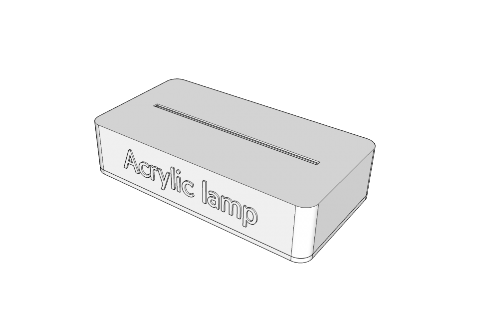
3D 모델링
하드웨어 메이킹과 소프트웨어 코딩을 마줬으니 이제 3D 모델링을 통해 아크릴 램프의 외관을 디자인할 차례입니다.
다른 프로젝트와 마찬가지로 3D 모델링 툴은 스케치업을 사용하였습니다.
자 그럼 어떻게 모델링을 진행하였는지 쓰윽 살펴볼까요~?
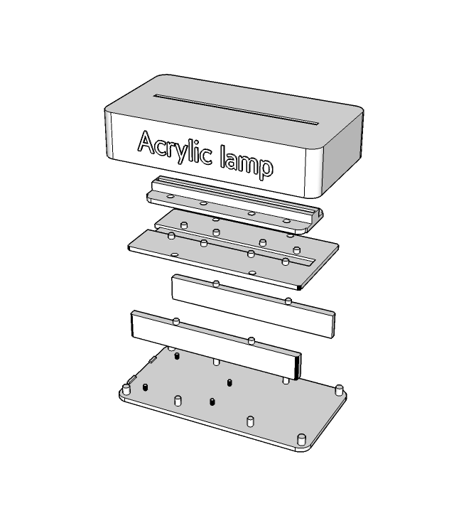
DIY 아크릴 램프의 구성은 위 사진과 같습니다.
비교적 간단한 파츠들로 나눠져있죠?
크게 밑판, neopixel 거치대, 그리고 덮개로 구성되어 있습니다.
각 각의 파츠들에 대해 알아볼까요? ;)
밑판
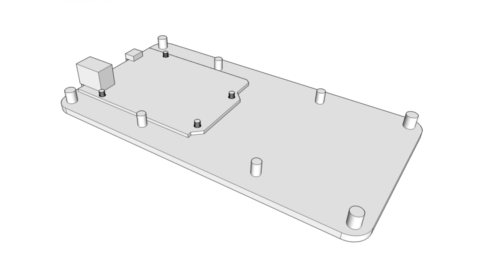
오렌지보드 BLE와 거치대, 덮개를 쉽게 결합하기 위해 홈을 만들어 주었습니다.
외곽의 4개의 기둥은 덮개와 결합되는 기둥이며, 내부의 4개의 기둥은 LED 거치대와 결합하기 위한 기둥입니다.
사진에서 알 수 있다시피 제일 작은 4개의 기둥은 오렌지보드 BLE를 고정시키기 위한 기둥입니다!
neopixel 거치대
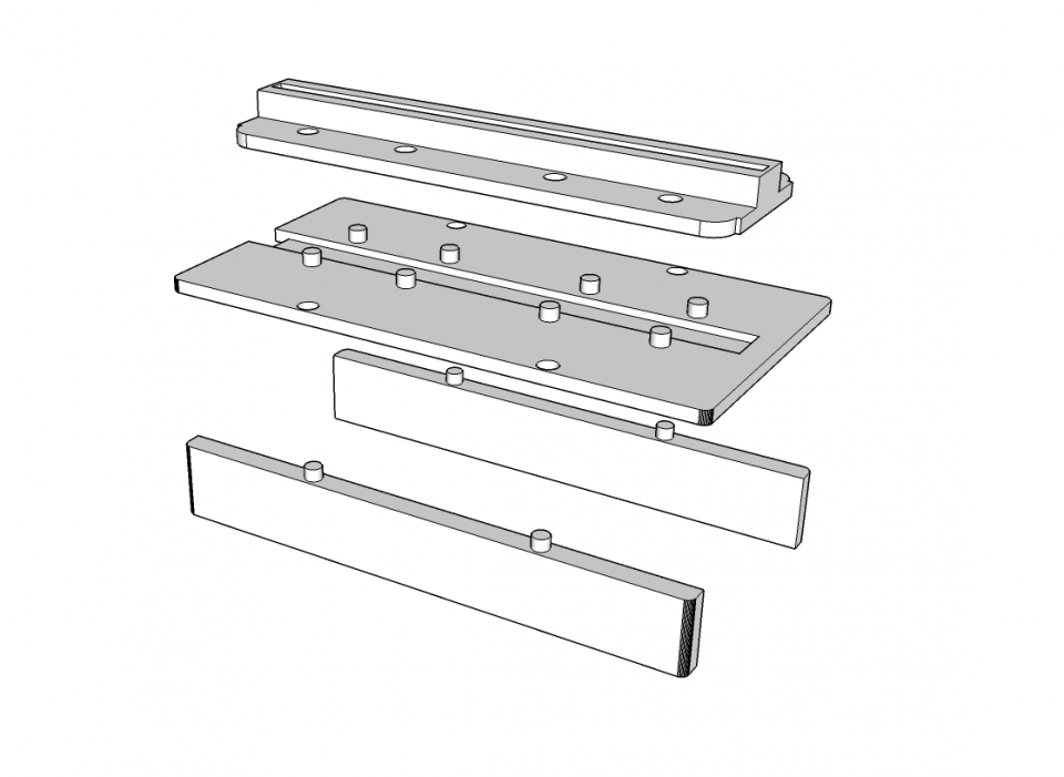
거치대의 구성은 위 사진과 같습니다.
- 사진에서 보이는 가장 아래 2개의 파츠 : neopixel LED와 오렌지보드 BLE와 wiring 하기 위해서는 공간이 필요하기 때문에 만들어 준 파츠입니다.
- 사진에서 보이는 중간의 파츠(LED 결합판) : neopixel LED를 붙일 파츠입니다. 가운데 홈에 neopixel strip LED를 붙여주면 됩니다.
- 사진에서 보이는 제일 위의 파츠(아크릴 고정대) : 아크릴을 고정시킬 파츠입니다. 아크릴이 흔들리지 않아야 하기 때문에 적당한 깊이를 잡아주어야 합니다.
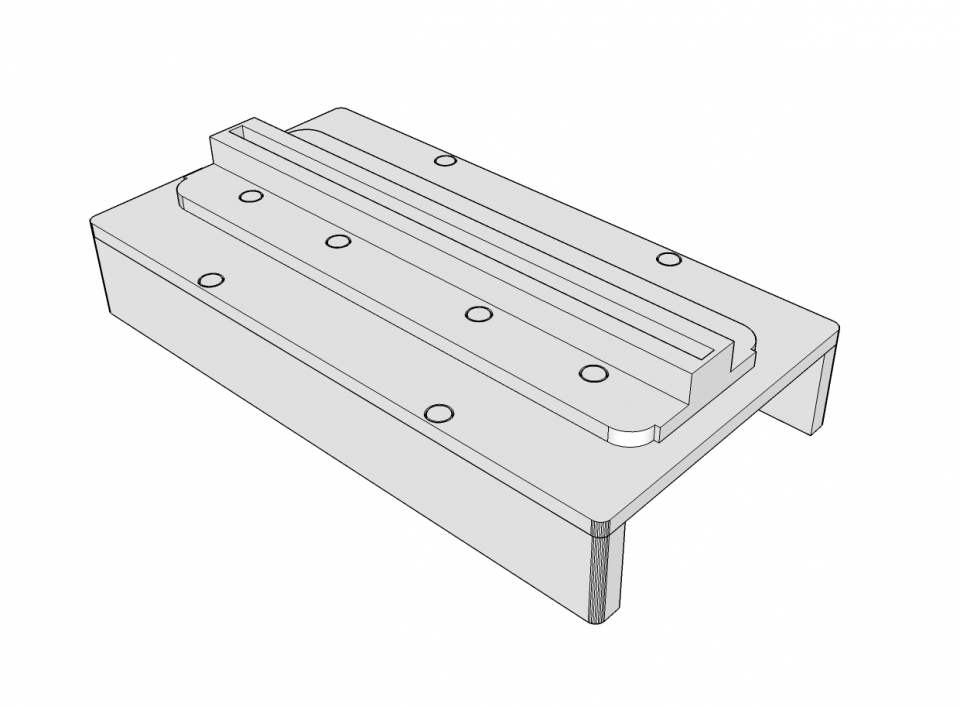
3개의 파츠가 결합된 모습은 아래와 같습니다.
덮개
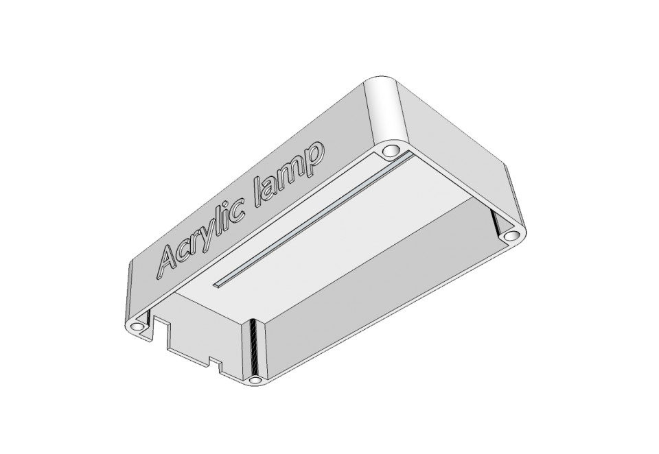
마지막으로 덮개 파츠입니다.
아크릴이 통과할 수 있겠금 윗 면에 공간을 뚫어줍니다.
외곽의 4개의 홈이 밑 판의 기둥과 결합되는 부분입니다! ;)
DIY 아크릴 램프의 파츠들까지 모두 모델링을 끝냈네요~ㅎㅎ
이 파츠들로 어떻게 아크릴 램프를 조립하는지 이해가 되지 않으신다구요?
백문이 불여일견!
자 이제 제작 과정을 소개하겠습니다!
제작 과정
3D 모델링 작업 후 3D 프린터로 파츠들을 출력하였습니다.
자 그럼 즐거운 조립 시간!
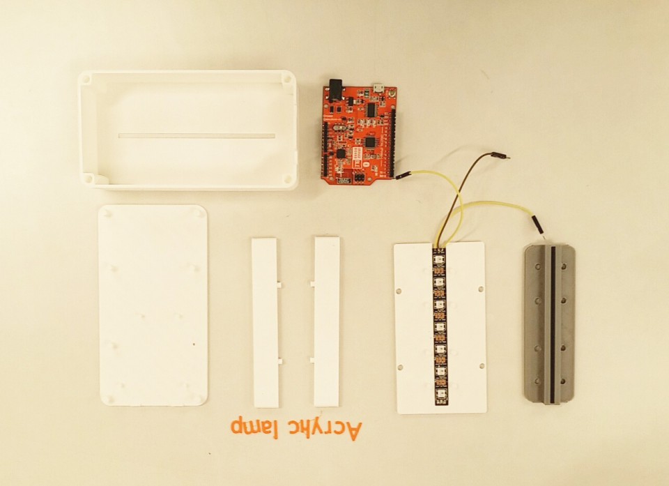
아크릴 램프에 사용될 파츠들입니다.
오잉? 아크릴 고정대만 왜 색이 다르냐구요?
LED의 빛이 옆으로 퍼져나가지 않도록 진한색으로 출력하였습니다 ;)
neopixel strip LED는 판에 부착해주었습니다!
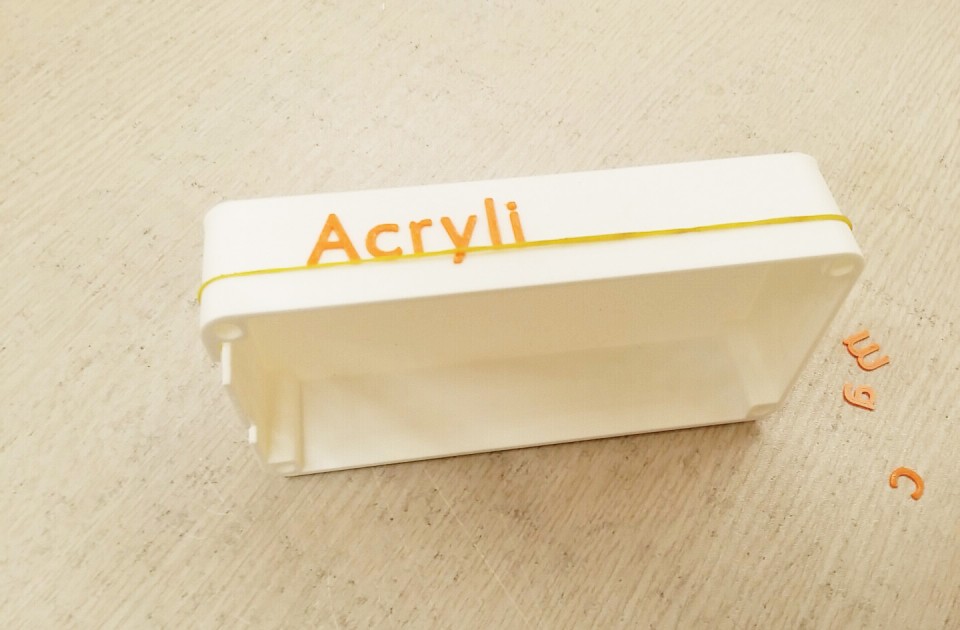

제일 먼저 덮개 부분에 글자들을 붙여주었습니다.
수평을 맞추기 위해 고무줄을 활용하였죠ㅎㅎ
흰색 바탕에 오렌지색 글자가 심심함을 잡아주는 것 같네요~ ;)
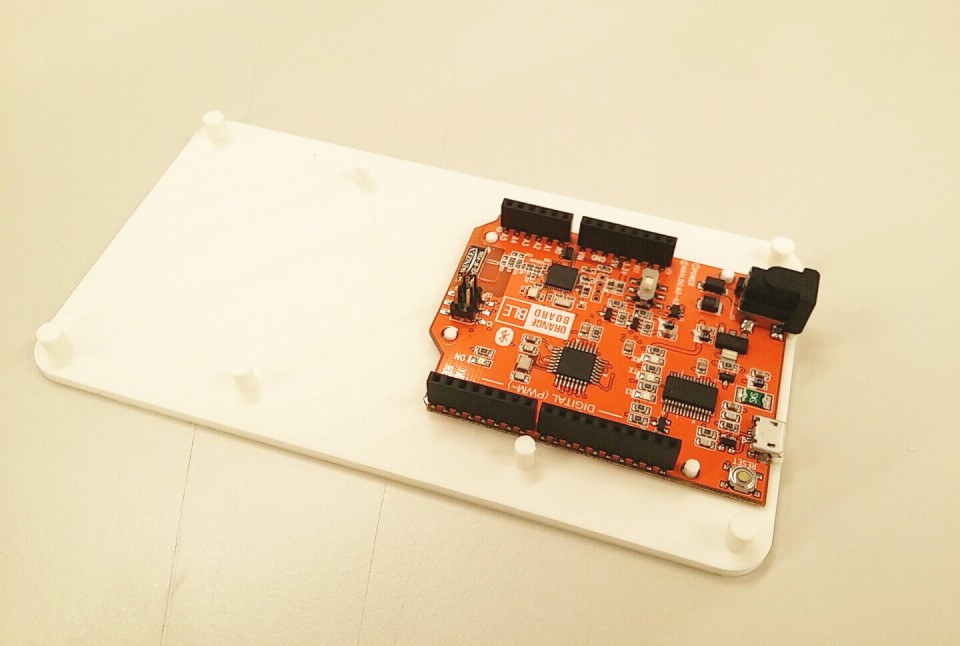
밑판의 기둥에 맞게 오렌지보드 BLE의 홈을 결합해줍니다.
이렇게 고정을 해줘야 USB나 DC jack을 끼고 뺄 때 보드가 움직이지 않습니다 ;)
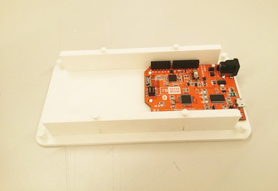
양 옆의 판을 밑판의 기둥에 맞게 껴줍니다. 공간이 넉넉하니 안에 건전지를 넣어서 바로 오렌지보드에 전원을 공급해주셔도 됩니다.
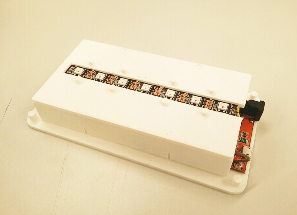
neopixel strip LED를 오렌지보드 BLE와 wiring 해주고, LED 고정판을 옆판의 홈에 맞게 결합해주었습니다.
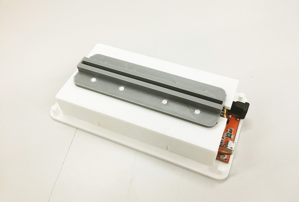
그 위에 아크릴 고정대를 결합해줍니다. 마친가지로 홈에 맞게 끼워주기만 하면 됩니다.
진한색으로 출력한 덕에 LED의 빛이 옆으로 확산되지 않고, 아크릴이 끼워지는 구멍으로만 확산되겠죠? ;)
마지막으로 덮개를 홈에 맞게 끼워주면 완성!!!
참 쉽쥬?
램프 부분이 완성되었으니 이제 아크릴을 재단 할 차례입니다.
저 같은 경우 레이저 컷팅을 해본 적이 없었는데, 이번 프로젝트 덕에 레이저 컷팅을 접할 수 있어 정말 유익한 시간이였네요! ㅎㅎ
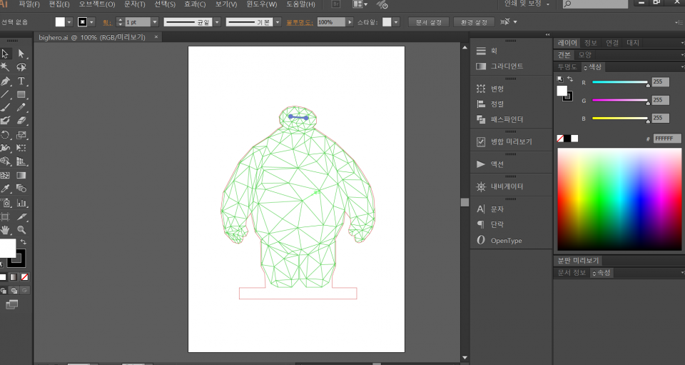
레이저 컷팅을 하기 위해서는 일러스트레이터로 Path 작업을 해주어야 합니다.
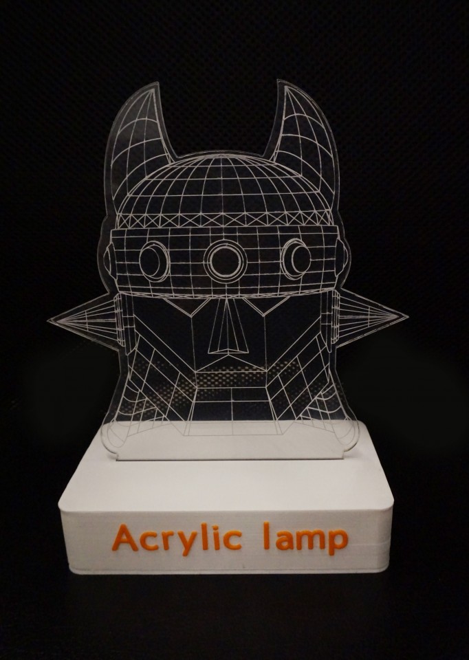
빅 히어로를 그려봤어요ㅎㅎ

제가 개인적으로 좋아하는 태권 V!!!(남자의 로망이죠ㅎㅎ)
꼭 뽑아보고 싶었는데 쉽지 않아 전전긍긍하고 있었는데 염소 할배님께서 3D 모델링을 진행해 Path로 변환시켜 주셨어요!
저는 그리드만 조금 추가하였습니다ㅎㅎ 고마워요! 염소할배님(굽신 굽신)
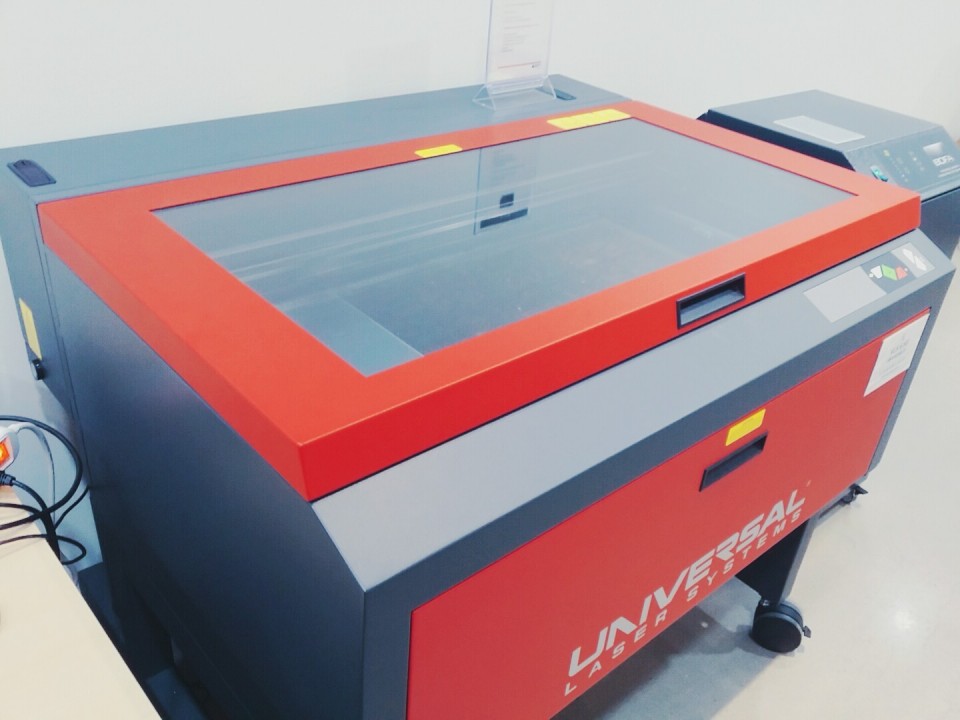
레이져 컷팅을 위해 무한 상상실을 여기 저기 찾아보다가 국립 현대 미술관에 있는 무한 상상실인 art fablab을 방문하였습니다.
공간도 너무 깔끔하고, 상주하시는 매니저 분들도 너무 친절히 가르쳐 주셨습니다.

레이져 커팅기 프로그램에 Path(일러스트레이터 파일 Ai)를 넣어주고, 출력을 합니다.

열심히 자르고 있는 레이져 컷팅기입니다ㅎㅎ 힘내!!!!


재단된 아크릴의 모습입니다. 정말 깔끔히 나와서 놀랐어요!ㅎㅎ
앞으로도 레이져컷팅기를 많이 활용해 볼 생각입니다! ;)
자 이제 아크릴까지 모든 제작 과정을 마쳤습니다.
이제 완성된 모습을 보는 일만 남았죠? 두구 두구 두구~ 개봉박두!
완성 모습
아크릴 램프의 램프부의 모습입니다!

이제 재단한 아크릴을 꽂아봐야겠죠? ;)
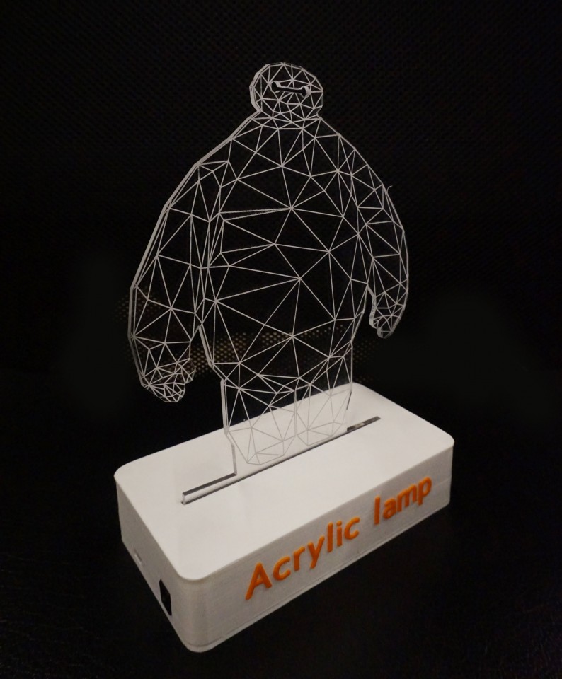
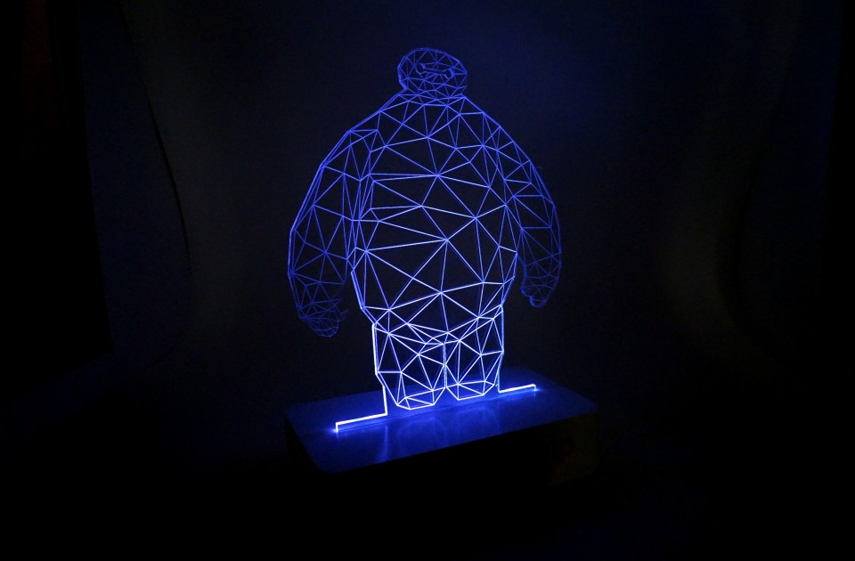
태권 V와 배이 맥스 아크릴을 램프에 결합한 모습은 아래와 같습니다!
아크릴이 정말 깔금히 재단되어서 뿌듯합니다!ㅎㅎ
소등된 아크릴 램프의 모습

램프는 역시 어두운 곳에서 켜야 진가를 발휘하죠!
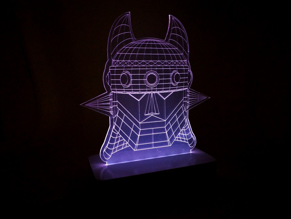
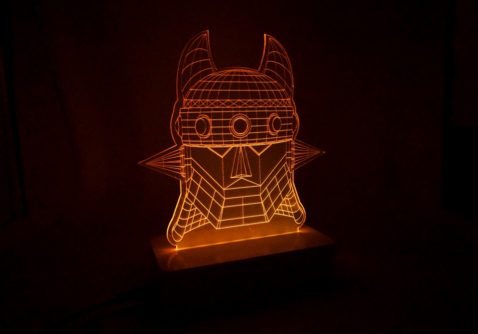
어두운 곳에서 점등한 아크릴 램프의 모습! 지금 바로 보시죠~ ;)
점등된 아크릴 램프의 모습
어플리케이션을 통해 램프의 색상을 선택할 수 있습니다! ;)
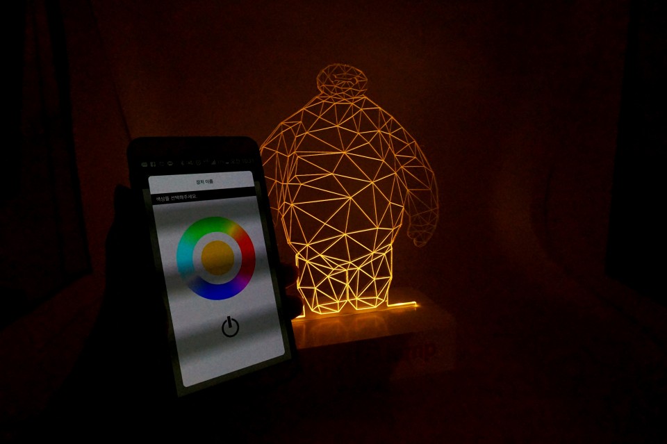
동영상
스마트폰 어플리케이션의 컬러휠을 터치해 아크릴 램프의 색상을 제어할 수 있습니다.
리소스
프로젝트에 사용된 소스들입니다. 이미지를 클릭하여 해당 파일을 다운받으세요!


마치며...
이번 프로젝트를 계기로 접해보지 못한 새로운 장비(레이져컷팅기)를 사용해볼 수 있었습니다 ;)
레이저 컷팅기의 경우 사용하기 어려워 보이지만, 조금만 해보면 3D 프린터만큼 쉽게 사용이 가능합니다!
3D 프린터와 레이저 컷팅기의 장점들을 잘 활용하면, 더 질 좋은 프로젝트를 진행 할 수 있겠죠?


Klant
 코코아팹, 오픈소스 하드웨어, 오렌지보드 BLE, 아크릴 램프, DIY, kocoafab, opensource hardware, orangeboard BLE, acrylic lamp
