2016-10-10 17:26:37

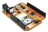
OrangeBoard WiFi는 기존 OrangeBoard에 WiFi모듈을 장착하여 하나의 보드안에서 아두이노의 기능과 WiFi를 사용할 수 있게 하였습니다.
아두이노에 수많은 데이터를 웹에서 가져올 수 있는 WiFi모듈을 결합하였기 때문에 사용자들은 기존의 아두이노보다 한 단계 더 넓은 범위를 바라보고 사용할 수 있습니다.
이번 글을 따라하기 위해서는 이전 글의 이해가 필요합니다.
(OrangeBoard WiFi사용하기(9) - OrangeBoard WiFi의 AP모드 사용하기 - http://kocoafab.cc/modify/tutorial/668?level=3)
이전글에서는 AP모드를 통해 두 대의 OrangeBoard WiFi를 통신하는 방법에 대해 알아보았습니다.
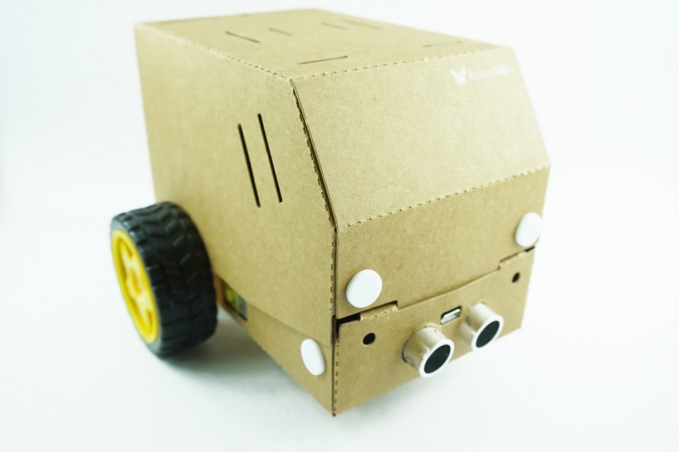
이번글에서는 이제 OrangeBoard WiFi를 응용하여 RC카를 블루투스가 아닌 WiFi통신으로 무선 제어하는 프로젝트를 제작해보도록 하겠습니다.
이번글에서 등장하는 RC카는 코코아팹의 RC카입니다! 꼭 아래 제품이 아니라 아두이노와 호환되는 RC카라면 어떤 제품이든지 가능합니다.
(RC카 제품 링크 : http://kocoafab.cc/product/rccar)
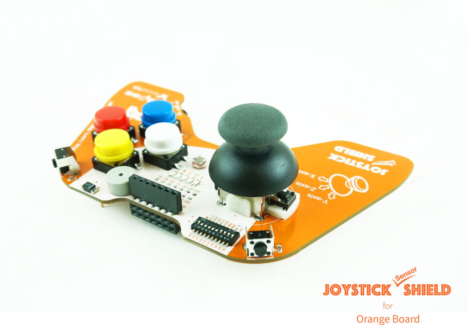
RC카를 제어할 컨트롤러는 코코아팹 조이스틱 센서쉴드를 사용합니다.
(조이스틱 센서쉴드 제품 링크 : http://kocoafab.cc/product/joystick)

| No | 부품명 | 수량 | 상세 설명 |
| 1 | OrangeBoard WiFi | 2 | WizFi250을 사용한 WiFi보드 |
| 2 | RC카 키트 | 1 | 코코아팹 RC카 키트 |
| 3 | 조이스틱 센서쉴드 | 1 |
| OrangeBoard WiFi | RC카 키트 | 조이스틱 센서쉴드 |
 |
 |
 |
이 프로젝트를 진행하려면 RC카가 필요합니다. 이 글에서는 코코아팹의 RC카 키트를 사용하기 때문에 RC카 키트 중심으로 글을 작성하겠습니다.
※ 위에서도 말했듯이 꼭 코코아팹RC카 키트가 아니더라도 아두이노로 제어가 가능한 RC카라면 그 제품을 쓰셔도 무방합니다.
RC카 조립에 관련된 글은 아래의 두 링크를 참조하세요!
RC카 키트 조립하기1 - http://kocoafab.cc/tutorial/view/647
RC카 키트 조립하기2 - http://kocoafab.cc/tutorial/view/648
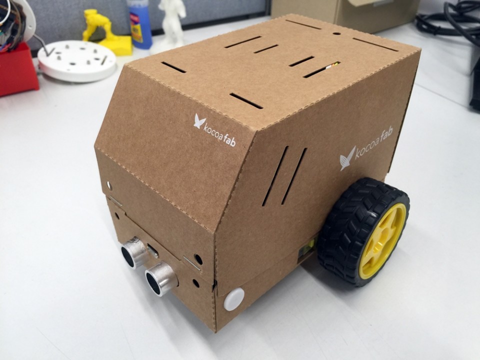
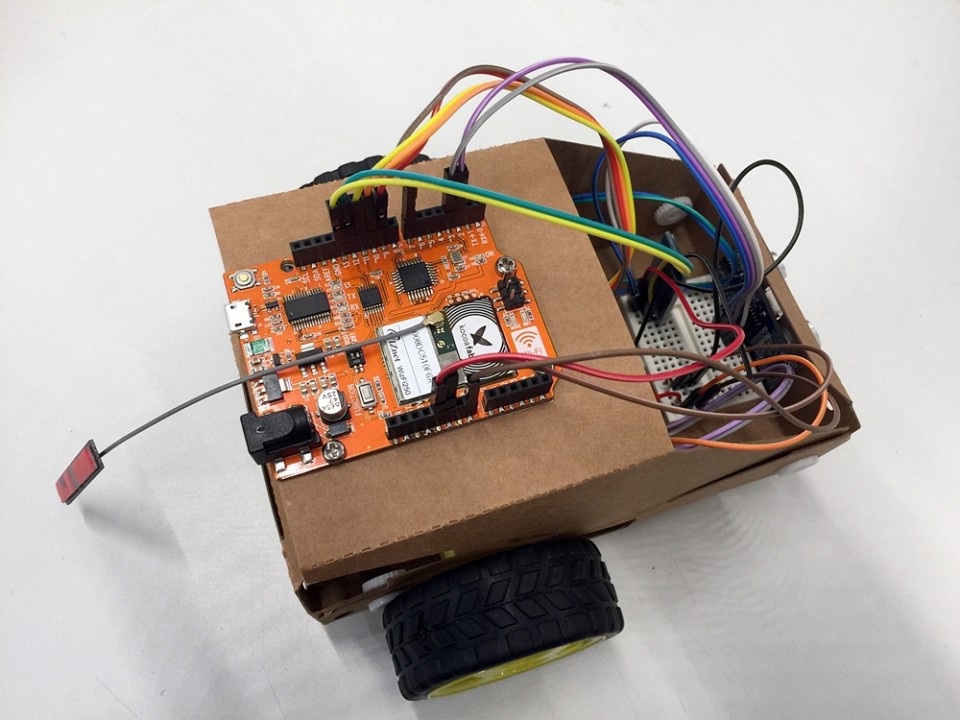
RC카 내부에는 몸체와 고정된 오렌지보드가 있습니다.
연결된 케이블을 제거하고 볼트를 제거하여 오렌지보드를 분리하고 OrangeBoard WiFi를 연결합니다.
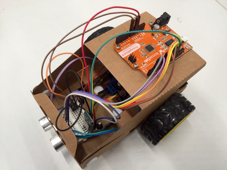
오렌지보드를 제거하고 OrangeBoard WiFi를 연결한 모습입니다.
위와 같이 OrangeBoard WiFi를 사용할때 주의할 점이 있습니다.
※ 아래의 핀은 WiFi모듈과 오렌지 보드 간 통신(SPI통신)을 위해 사용되는 핀이니 사용이 불가한 점을 유의해야 합니다.
혹시 아래 핀에 연결된 선이 있다면 사용이 중복되기 때문에 다른 핀에 연결해야 합니다.
| Pin Number | WizFi250 |
| D4 | WIFI_SS |
| D2 | WIFI_RESET |
| D3 | WIFI_DATA_READY(GPIO14) |
| D11 | WIFI_MOSI |
| D13 | WIFI_SCK |
| D12 | WIFI_MISO |
RC카 준비가 끝났으면 RC카를 제어할 컨트롤러가 필요합니다.
컨트롤러는 OrangeBoard WiFi와 조이스틱 센서쉴드를 사용합니다.
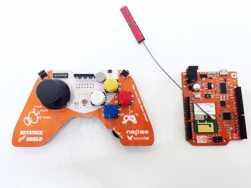
아래와 결합하면 하나의 컨트롤러로 제작합니다.
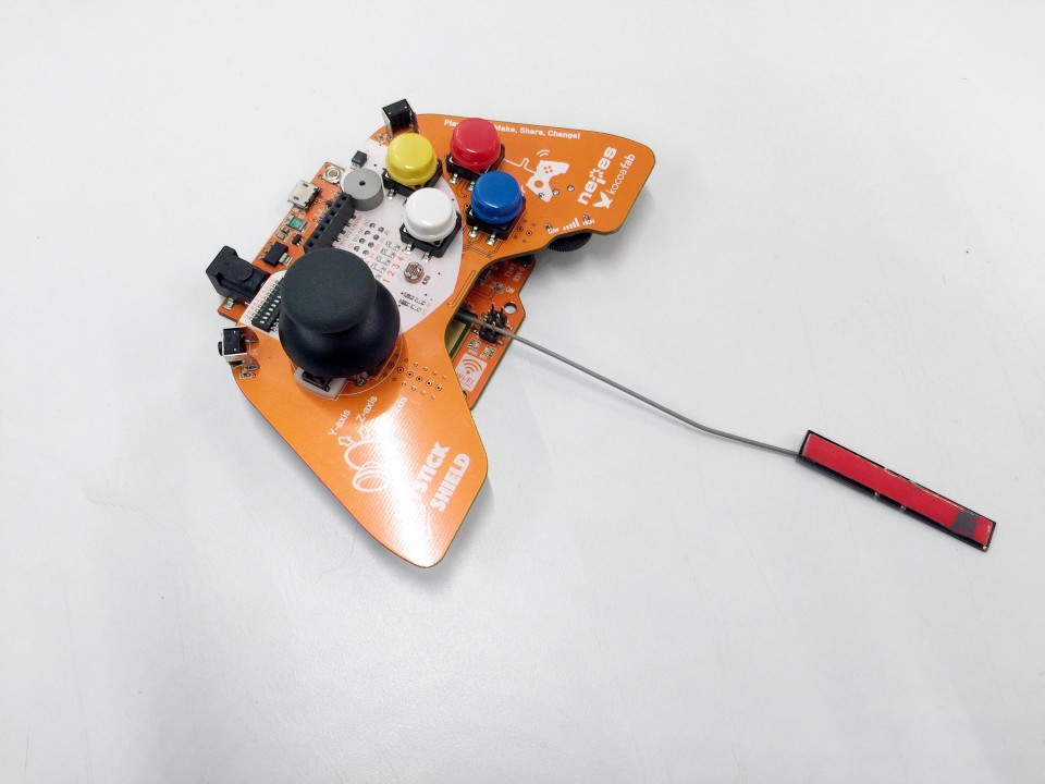
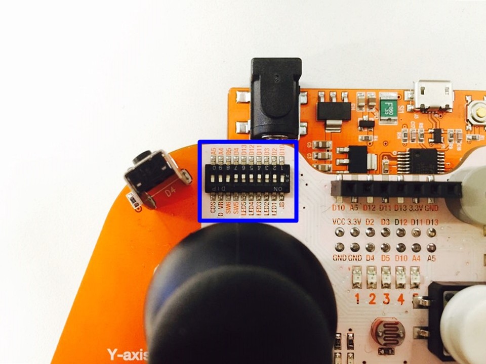
※ 조이스틱 센서쉴드를 사용할때 위에서 설명한 WiFi보드의 사용불가한 핀을 신경써서 아래 파란 박스안의 스위치를 바꿔주어야 합니다.
스위치가 총 10개가 존재하는데 스위치를 아래로 내릴 경우 'ON', 스위치를 위로 올릴 경우 'OFF'입니다.
D2, D3, D4, D11, D12, D13핀에 해당하는 스위치를 위로 올려야 합니다. 그냥 사용할 경우 WiFi연결이 되지 않음을 유의하세요!
#include <SPI.h>
#include <WizFi250.h>
#include <WizFi250Udp.h>


char ssid[] = "DIR-815_Wiznet";            // your network SSID (name)
char pass[] = "12345678";        // your network password
int status = WL_IDLE_STATUS;     // the Wifi radio's status

unsigned int localPort = 10002;  // local port to listen on

char packetBuffer[255];          // buffer to hold incoming packet
char ReplyBuffer[] = "ACK";      // a string to send back

WiFiUDP Udp;

void printWifiStatus();

//RCcar motor Pin
const int motorLeftF = 7;
const int motorLeftB = 6;
const int motorRightF = 8;
const int motorRightB = 9;

void setup() {
  // initialize serial for debugging
  Serial.begin(115200);

  WiFi.init();

  // check for the presence of the shield:
  if (WiFi.status() == WL_NO_SHIELD) {
    Serial.println("WiFi shield not present");
    // don't continue:
    while (true);
  }

  // attempt to connect to WiFi network
  while ( status != WL_CONNECTED) {
    Serial.print("Attempting to connect to WPA SSID: ");
    Serial.println(ssid);
    // Connect to WPA/WPA2 network
    status = WiFi.beginAP(ssid, 10, pass, ENC_TYPE_WPA2_PSK);
  }

  Serial.println("Connected to wifi");
  printWifiStatus();

  Serial.println("\nStarting connection to server...");
  // if you get a connection, report back via serial:
  Udp.begin(localPort);

  Serial.print("Listening on port ");
  Serial.println(localPort);

  pinMode(motorRightF, OUTPUT);
  pinMode(motorRightB, OUTPUT);
  pinMode(motorLeftF, OUTPUT);
  pinMode(motorLeftB, OUTPUT);
}

void loop() {

  // if there's data available, read a packet
  int packetSize = Udp.parsePacket();
  if (packetSize)
  {
    Serial.print("Received packet of size ");
    Serial.println(packetSize);
    Serial.print("From ");
    IPAddress remoteIp = Udp.remoteIP();
    Serial.print(remoteIp);
    Serial.print(", port ");
    Serial.println(Udp.remotePort());

    int len = Udp.read(packetBuffer, 200);
    if ( len > 0 ) {
      packetBuffer[len] = 0;

    }
    Serial.println("Contents:");
    Serial.println(packetBuffer);
    if(packetBuffer[0] == 'F') {
      digitalWrite(6,HIGH);
      digitalWrite(9,HIGH);
      digitalWrite(7,LOW);
      digitalWrite(8,LOW);
    }
    else if(packetBuffer[0] == 'B') {
      digitalWrite(7,HIGH);
      digitalWrite(8,HIGH);
      digitalWrite(6,LOW);
      digitalWrite(9,LOW);
    }
    else if(packetBuffer[0] == 'N') {
      digitalWrite(7,LOW);
      digitalWrite(8,LOW);
      digitalWrite(6,LOW);
      digitalWrite(9,LOW);
    }
    else if(packetBuffer[0] == 'R') {
      digitalWrite(7,LOW);
      digitalWrite(8,HIGH);
      digitalWrite(6,HIGH);
      digitalWrite(9,LOW);
    }
    else if(packetBuffer[0] == 'L') {
      digitalWrite(7,HIGH);
      digitalWrite(8,LOW);
      digitalWrite(6,LOW);
      digitalWrite(9,HIGH);
    }

    // send a reply, to the IP address and port that sent us the packet we received
    Udp.beginPacket(Udp.remoteIP(), Udp.remotePort());
    Udp.write(ReplyBuffer);
    Udp.endPacket();
  }
}


void printWifiStatus() {
  // print the SSID of the network you're attached to:
  Serial.print("SSID: ");
  Serial.println(WiFi.SSID());

  // print your WiFi shield's IP address:
  IPAddress ip = WiFi.localIP();
  Serial.print("IP Address: ");
  Serial.println(ip);

  // print the received signal strength:
  long rssi = WiFi.RSSI();
  Serial.print("signal strength (RSSI):");
  Serial.print(rssi);
  Serial.println(" dBm");
}
#include <SPI.h>
#include "WizFi250.h"
#include "WizFi250Udp.h"

char ssid[] = "DIR-815_Wiznet";  // your network SSID (name)
char pass[] = "12345678";        // your network password
int status = WL_IDLE_STATUS;     // the Wifi radio's status

char timeServer[] = "192.168.12.101";  // NTP server
unsigned int localPort = 2390;        // local port to listen for UDP packets

const int NTP_PACKET_SIZE = 48;  // NTP timestamp is in the first 48 bytes of the message

char packetBuffer[NTP_PACKET_SIZE]; // buffer to hold incoming and outgoing packets

// A UDP instance to let us send and receive packets over UDP
WiFiUDP Udp;

unsigned long sendNTPpacket(char *ntpSrv);

void setup()
{
  // initialize serial for debugging
  Serial.begin(115200);

  WiFi.init();

  // check for the presence of the shield
  if (WiFi.status() == WL_NO_SHIELD) {
    Serial.println("WiFi shield not present");
    // don't continue
    while (true);
  }

  // attempt to connect to WiFi network
  while ( status != WL_CONNECTED) {
    Serial.print("Attempting to connect to WPA SSID: ");
    Serial.println(ssid);
    // Connect to WPA/WPA2 network
    status = WiFi.begin(ssid, pass);
  }

  pinMode(A2, INPUT);
  pinMode(A3, INPUT);
  pinMode(8, INPUT);
  pinMode(9, INPUT);

  // you're connected now, so print out the data
  Serial.println("You're connected to the network");

  Udp.begin(localPort);
}

void loop()
{
  sendNTPpacket(timeServer); // send an NTP packet to a time server
  // wait to see if a reply is available
  delay(50);

  Serial.println(Udp.parsePacket());
  // wait ten seconds before asking for the time again
  delay(1);
}

unsigned long sendNTPpacket(char *ntpSrv)
{
  int joystickH = analogRead(A0);
  int joystickV = analogRead(A1);
  memset(packetBuffer, 0, NTP_PACKET_SIZE);
  if (joystickH > 800) {
    Serial.println("Right");
    packetBuffer[0] = 'R';
  }
  else if (joystickH < 300) {
    Serial.println("Left");
    packetBuffer[0] = 'L';
  }
  else if (joystickV > 800) {
    Serial.println("Forward");
    packetBuffer[0] = 'F';
  }
  else if (joystickV < 300) {
    Serial.println("Backward");
    packetBuffer[0] = 'B';
  }
  else {
    Serial.println("Natural");
    packetBuffer[0] = 'N';
  }
  Udp.beginPacket(ntpSrv, 10002); //NTP requests are to port 123
  Udp.write(packetBuffer, NTP_PACKET_SIZE);
  Udp.endPacket();
}
RC카와 조이스틱의 통신은 신뢰성이 그다지 중요한 요소가 아닌, 속도가 중요하기 때문에 UDP통신을 사용하였습니다.
사실 TCP로 해도 큰 차이는 없지만 UDP통신이 코드상으로 약간 편하게 되있습니다 :)
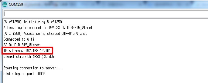
RC카 코드를 실행하면 시리얼 모니터 창에서 아래와 같이 출력됩니다.
IP Address가 현재 RC카 할당된 IP이며 조이스틱이 출력된 IP Address를 통해 RC카에 접속하면 서로 1:1 연결이 됩니다.
(혹시 위 코드를 실행시켰을 시, 연결이 되지 않는다면 아래의 IP Address를 확인하여 조이스틱 코드에서 접속 IP를 변경하세요.)
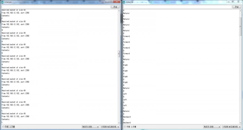
서로 통신할 경우 아래와 같이 시리얼모니터 창 2개로 통신하는 것을 확인해 볼 수 있습니다.
(좌측이 RC카, 우측이 조이스틱입니다.)

kocoafabeditor 
항상 진취적이고, 새로운 것을 추구하는 코코아팹 에디터입니다!
 WiFi, WiFi보드, Arduino, OrangeWiFi, APmode, AP, RC카, 조이스틱, 센서 쉴드, Control


