
ZigBee통신으로 사람을 무선 인식하여 LEDmatrix에 메시지를 띄워보기
2014-11-14 17:20:14
개요
개요
zigBee는 근거리 통신을 지원하는 IEEE 802.15.4 표준 중 하나로 zigbee모듈만 있으면 손쉽게 무선 통신을 가능하게 해준다.통신거리 또한 10m~100m까지 지원되므로 거리 또한 준수한 편에 속한다.

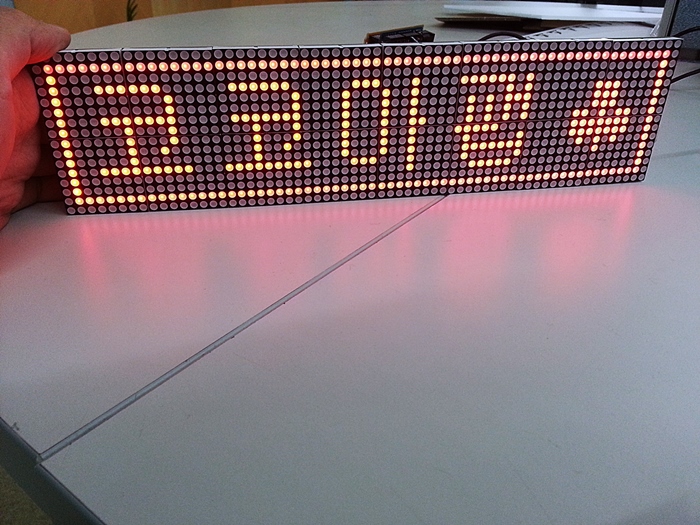
이번에는 zigbee의 송신부에 초음파 센서를 장착하여 물체나 사람을 인식하게 하고
수신부에게 물체나 사람의 인식여부를 전달하여 LEDmatrix를 통해 메시지를 띄워보는 프로젝트를 해보자.
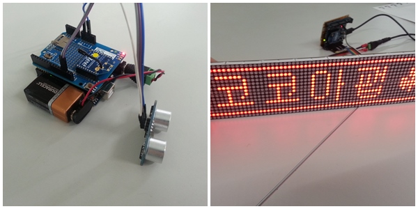
통신이 들어가면 복잡해 보이지만 실상 흐름도를 보면 상당한 단순한 프로젝트이다.
데이터 전송은 초음파의 인식여부가 전부이며 인식이 됐다면 LEDmatrix에 값을 띄워주면 된다.
동영상
필요한 사전 지식
시리얼 통신zigbee
LED matrix
초음파 센서
부품 목록
| NO | 부품명 | 수량 | 상세설명 |
| 1 | 아두이노 | 2 | 오렌지 보드 |
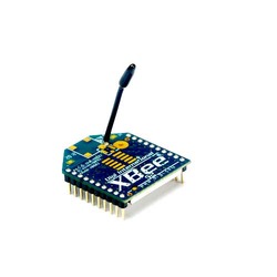
| 2 | zigbee 모듈 | 2 | Digi international Xbee S1 |
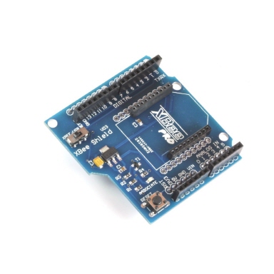
| 3 | zigbee 쉴드 | 2 | |
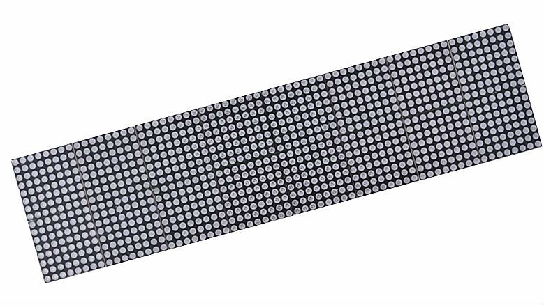
| 4 | 64x16 LED matrix | 1 | 3.75mm 64x16 Dot Matrix LED Display |
| 5 | 초음파 센서 | 1 | HC-SR04 |
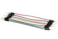
| 6 | 점퍼케이블 | 15 | 점퍼케이블 |
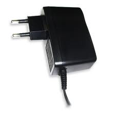
| 7 | 아답터 | 1 | DC 5V |
| 8 | 9v 건전지 | 1 |
| 부품명 | 아두이노 | zigbee 모듈 | zigbee 쉴드 | 64X16 LED matrix |
| 부품 사진 | 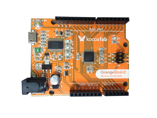 |
 |
 |
 |
| 부품명 | 초음파 센서 | 점퍼케이블 | 아답터 | 9v 건전지 |
| 부품 사진 | 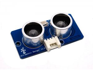 |
 |
 |
 |
하드웨어 making
브레드 보드
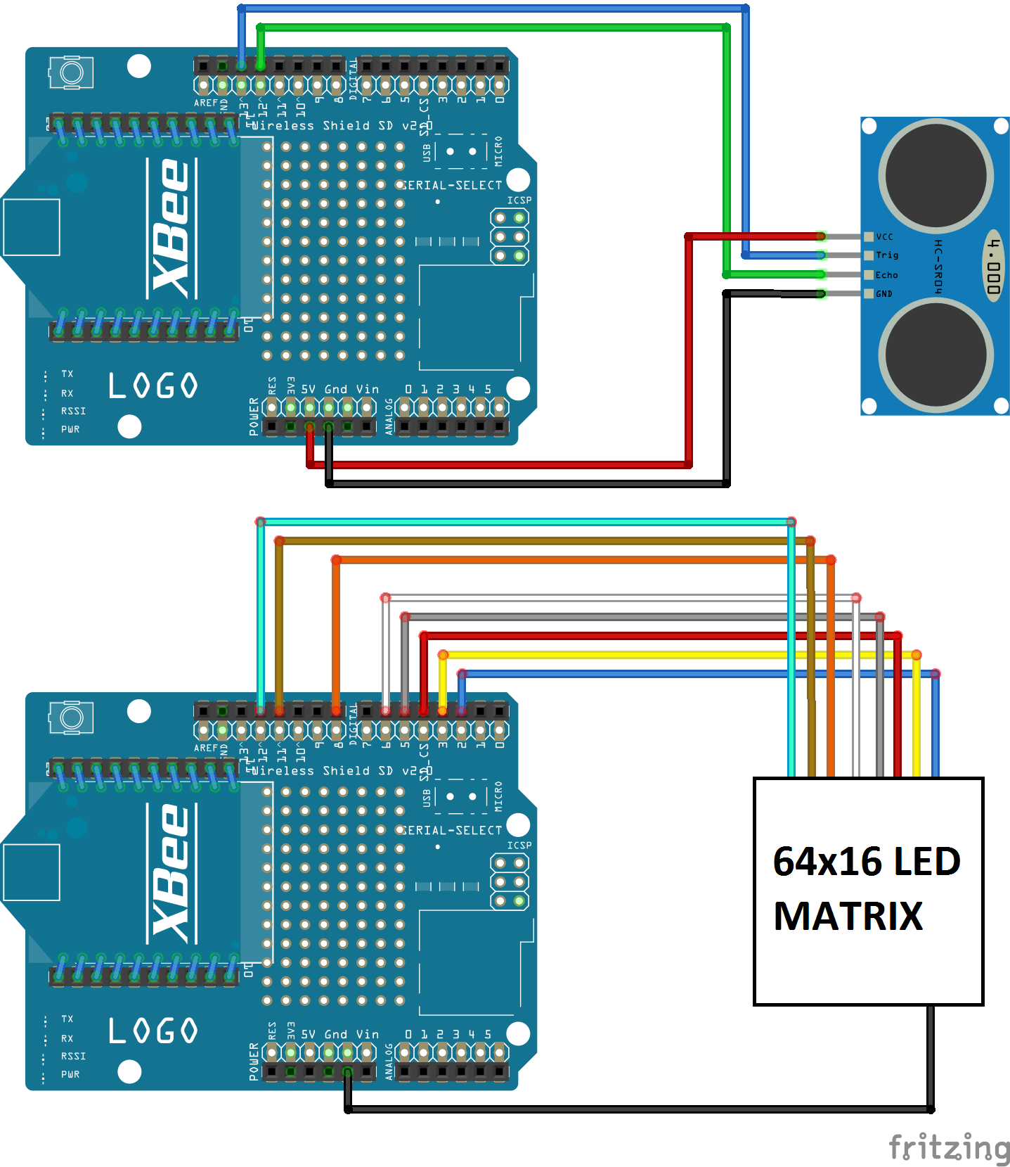
핀 연결에 대해서는 튜토리얼을 참고하면 더 자세한 내용을 볼 수 있다.
64x16 LEDmatrix 사용하기 <- 튜토리얼 링크
초음파 센서 사용하기 <- 튜토리얼 링크
소프트웨어 coding
송신부(초음파 센서)
int echoPin = 12;
int trigPin = 13;
//초음파 센서의 핀번호를 설정한다.

void setup(){
  Serial.begin(9600);
  pinMode(trigPin, OUTPUT);
  pinMode(echoPin, INPUT);
// trig를 출력모드로 설정, echo를 입력모드로 설정
}

void loop(){
  float duration;
  int distance;
  char signal = 'A';
  digitalWrite(trigPin, HIGH);
  delay(10);
  digitalWrite(trigPin, LOW);
  // 초음파를 보낸다. 다 보내면 echo가 HIGH 상태로 대기하게 된다.

  duration = pulseIn(echoPin, HIGH); // echoPin 이 HIGH를 유지한 시간을 저장 한다.
  distance = ((float)(340 * duration) / 10000) / 2;  // HIGH 였을 때 시간(초음파가 보냈다가 다시 들어온 시간)을 가지고 거리를 계산 한다.

  if(distance < 100) { //인지한 거리가 100이하로 측정될 경우 signal을 zigbee통신을 통해 전송한다.
    Serial.print(signal);
  }

  delay(500);
}
여기서는 임의로 거리를 100로 잡고 100을 기준으로 100 이하의 값이 초음파 센서에서 측정 될 경우 수신부에게 특정신호(알파벳 A)를 보내도록 만들었다.
수신수(LEDmatrix)
//Author: cantone-electonics
//More information welcome to : http://www.canton-electronics.com
//Arduino 1.0.4
//Arduino uno R3
//64x16 Matrix LED

#define COL_PIXEL     64
#define ROW_PIXEL     16

int latchPin=8; //LT
int clockPin=12;//SK
int dataPin=11; //R1

int en_74138 = 2;
int la_74138 = 3;
int lb_74138 = 4;
int lc_74138 = 5;
int ld_74138 = 6;

unsigned int ROW_xPixel;
unsigned int ROW_num;
unsigned char Col_num_1;
unsigned char Col_num_2;
unsigned char Col_num_3;
unsigned char Col_num_4;
unsigned char Col_num_5;
unsigned char Col_num_6;
unsigned char Col_num_7;
unsigned char Col_num_8;

char ch;

//Data code: Horizontal modulus ,Bytes reverse order
unsigned char  Bmp1[]=
{

0x0 , 0x0 , 0x0 , 0x0 , 0x0 , 0x0 , 0x0 , 0x0
 , 0x0 , 0x0 , 0x0 , 0x0 , 0x0 , 0x0 , 0x0 , 0x0
 , 0xfc , 0xFF , 0xFF , 0xFF , 0xFF , 0xFF , 0xFF , 0xFF
 , 0xFF , 0xFF , 0xFF , 0xFF , 0xFF , 0xFF , 0xFF , 0x3F
 , 0x0c , 0x0 , 0x0 , 0x0 , 0x0 , 0x0 , 0x0 , 0x0
 , 0x0 , 0x0 , 0x0 , 0x0 , 0x0 , 0x0 , 0x0 , 0x30
 , 0x0c , 0xfc , 0x3F , 0x0 , 0xfc , 0x3F , 0x0 , 0xfc
 , 0xc0 , 0x0 , 0xFF , 0xCF , 0x0 , 0x0 , 0x0 , 0x30
 , 0x0c , 0x0 , 0xc0 , 0x0 , 0x0 , 0xc0 , 0x0 , 0x03
 , 0xc3 , 0x0 , 0x0 , 0xcc , 0x0 , 0xc0 , 0x0F , 0x30
 , 0x0c , 0x0 , 0xc0 , 0x0 , 0x0 , 0xc0 , 0x0 , 0x03
 , 0xc3 , 0x0 , 0xcc , 0xfc , 0x0 , 0xc0 , 0x0F , 0x30
 , 0x0c , 0xfc , 0xFF , 0x0 , 0xfc , 0xFF , 0x0 , 0x03
 , 0xc3 , 0x0 , 0xcc , 0xcc , 0x0 , 0xc0 , 0x0F , 0x30
 , 0x0c , 0xc0 , 0xc0 , 0x0 , 0xc0 , 0xc0 , 0x0 , 0x03
 , 0xc3 , 0x03 , 0xcc , 0xcc , 0x0 , 0x3c , 0xF3 , 0x30
 , 0x0c , 0xc0 , 0xc0 , 0x0 , 0xc0 , 0xc0 , 0x0 , 0x03
 , 0xc3 , 0x0 , 0xFF , 0x03 , 0x0 , 0xfc , 0xFF , 0x30
 , 0x0c , 0xc0 , 0x30 , 0x0 , 0xc0 , 0x30 , 0x0 , 0x03
 , 0xc3 , 0x0 , 0x0c , 0xc0 , 0x0 , 0xfc , 0xFF , 0x30
 , 0x0c , 0xc0 , 0x0 , 0x0 , 0xc0 , 0x0 , 0x0 , 0x03
 , 0xc3 , 0x0 , 0xfc , 0xFF , 0x0 , 0x30 , 0x33 , 0x30
 , 0x0c , 0xFF , 0xFF , 0x03 , 0xFF , 0xFF , 0x03 , 0xfc
 , 0xc0 , 0x0 , 0x0c , 0xc0 , 0x0 , 0x0 , 0x03 , 0x30
 , 0x0c , 0x0 , 0x0 , 0x0 , 0x0 , 0x0 , 0x0 , 0x0
 , 0xc0 , 0x0 , 0xf0 , 0x3F , 0x0 , 0x0 , 0x0 , 0x30
 , 0x0c , 0x0 , 0x0 , 0x0 , 0x0 , 0x0 , 0x0 , 0x0
 , 0x0 , 0x0 , 0x0 , 0x0 , 0x0 , 0x0 , 0x0 , 0x30
 , 0xfc , 0xFF , 0xFF , 0xFF , 0xFF , 0xFF , 0xFF , 0xFF
 , 0xFF , 0xFF , 0xFF , 0xFF , 0xFF , 0xFF , 0xFF , 0x3F
 , 0x0 , 0x0 , 0x0 , 0x0 , 0x0 , 0x0 , 0x0 , 0x0
 , 0x0 , 0x0 , 0x0 , 0x0 , 0x0 , 0x0 , 0x0 , 0x0
};


void shiftOut(unsigned char dataOut)
{

    for(int i=0;i<=7;i++)
   {
      PORTB &=~(1<<(clockPin-8));//equate digitalWrite(clockPin,LOW);

     if(dataOut & (0x01<<i))  PORTB |=1<<(dataPin-8); //equate digitalWrite(dataPin,HIGH);
     else  PORTB &=~(1<<(dataPin-8));//equate digitalWrite(dataPin,LOW);

     PORTB |=1<<(clockPin-8);//equate digitalWrite(clockPin,HIGH);

   }
}

//Combine 2 bits/pixel to 1 bits/pixel
unsigned char Combine_2BitsTo1Bit(unsigned char num,unsigned char *BMP)
{

  unsigned char Col_num_tem_1;
  unsigned char Col_num_tem_2;
  unsigned int Col_num_tem = 0;
  unsigned char i=0;
  unsigned char Col_num_1bit = 0x00;

  Col_num_tem_1 = *(BMP+num);
  Col_num_tem_2 = *(BMP+num+1);

  Col_num_tem = Col_num_tem_1;
  Col_num_tem |= (Col_num_tem_2 << 8);

 for(i=0;i<8;i++)
  {
    if(Col_num_tem&(0x0003<<i*2)) Col_num_1bit |= (0x01<<i);
  }
  return ~Col_num_1bit;
}

//display one picture
void display_martix(unsigned char *BMP)
{
  //Display count
  unsigned int dis_cnt=256;
  unsigned int i;

   for(i=0;i<dis_cnt*16;i++)
   {

     digitalWrite(en_74138, HIGH);//Turn off display

     //Col scanning
    shiftOut(Col_num_1);
    shiftOut(Col_num_2);
    shiftOut(Col_num_3);
    shiftOut(Col_num_4);
    shiftOut(Col_num_5);
    shiftOut(Col_num_6);
    shiftOut(Col_num_7);
    shiftOut(Col_num_8);

    digitalWrite(latchPin, LOW);
    digitalWrite(latchPin, HIGH);

    //Row scanning
    // AVR Port Operation
    PORTD = ((ROW_xPixel << 3 ) & 0X78) | (PORTD & 0X87);//Write PIN 3 4 5 6 la_74138 lb_74138 lc_74138 ld_74138

    digitalWrite(en_74138, LOW);//Turn on display


    if(ROW_xPixel==15) ROW_xPixel=0; else ROW_xPixel++;

   /*
   // Single color,1 bits/pixel
   Col_num_1=~BMP[(COL_PIXEL/8)*ROW_xPixel];
   Col_num_2=~BMP[(COL_PIXEL/8)*ROW_xPixel+1];
   Col_num_3=~BMP[(COL_PIXEL/8)*ROW_xPixel+2];
   Col_num_4=~BMP[(COL_PIXEL/8)*ROW_xPixel+3];
   Col_num_5=~BMP[(COL_PIXEL/8)*ROW_xPixel+4];
   Col_num_6=~BMP[(COL_PIXEL/8)*ROW_xPixel+5];
   Col_num_7=~BMP[(COL_PIXEL/8)*ROW_xPixel+6];
   Col_num_8=~BMP[(COL_PIXEL/8)*ROW_xPixel+7];
 */

   //Single color,2 bits/pixel
   Col_num_1 = Combine_2BitsTo1Bit((COL_PIXEL/8)*ROW_xPixel*2,BMP);
   Col_num_2 = Combine_2BitsTo1Bit((COL_PIXEL/8)*ROW_xPixel*2+2,BMP);
   Col_num_3 = Combine_2BitsTo1Bit((COL_PIXEL/8)*ROW_xPixel*2+4,BMP);
   Col_num_4 = Combine_2BitsTo1Bit((COL_PIXEL/8)*ROW_xPixel*2+6,BMP);
   Col_num_5 = Combine_2BitsTo1Bit((COL_PIXEL/8)*ROW_xPixel*2+8,BMP);
   Col_num_6 = Combine_2BitsTo1Bit((COL_PIXEL/8)*ROW_xPixel*2+10,BMP);
   Col_num_7 = Combine_2BitsTo1Bit((COL_PIXEL/8)*ROW_xPixel*2+12,BMP);
   Col_num_8 = Combine_2BitsTo1Bit((COL_PIXEL/8)*ROW_xPixel*2+14,BMP);

  // delayMicroseconds(1000);

  }

}

void setup()
{
  pinMode(latchPin,OUTPUT);
  pinMode(clockPin,OUTPUT);
  pinMode(dataPin,OUTPUT);

  pinMode(en_74138,OUTPUT);
  pinMode(la_74138,OUTPUT);
  pinMode(lb_74138,OUTPUT);
  pinMode(lc_74138,OUTPUT);
  pinMode(ld_74138,OUTPUT);

  digitalWrite(en_74138, LOW);

  // AVR Port Settings
  DDRD |= 0x78; //Set PIN 3 4 5 6 output

  Serial.begin(9600);
}


void loop()
{
  if(Serial.available()) { //전송된 데이터가 존재하는지 확인한다.
    ch = Serial.read(); //전송된 데이터가 있으면 ch에 저장
    if(ch == 'A') { //저장된 값이 'A'일 경우 코코아팹 메시지 출력
      display_martix(Bmp1); //kocoafab
    }
  }
}
loop()안의 코드만 보면 된다.
수신부에서는 Serial.available()을 통해 전송된 데이터가 있는지 검사하고 전송된 데이터가 존재할 경우 그 값을 확인한다.
확인된 값이 송신부에서 보낸 값으로 확인될 경우 display_matrix()를 통해 지정된 화면을 LEDmatrix에 띄우게 된다.


수박쨈
 아두이노, zigbee, LEDmatrix, 초음파 센서
