2015-06-23 17:53:20

스크래치는 스퀵을 기반으로 MIT Media Lab에서 개발한 8세 이상의 어린이들의 소프트웨어 교육을 위한 개발 툴입니다.
스크래치를 사용하면 이야기책, 애니메이션, 게임, 다양한 프로그램등을 손으로 직접 만들수 있고, 또한 이를 전 세계 사람들과 공유 할 수 있습니다.

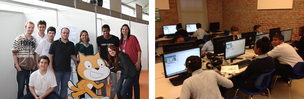
<전 세계 사람들이 공유한 스크래치 프로젝트>
간단한 블럭을 이용하기 때문에 남녀노소 누구나 쉽게 프로그래밍을 하면서 프로그래밍의 개념을 쉽게 익힐 수 있기 때문에 세계 여러곳의 학교에서 교육용으로 쓰이고 있습니다.
이런 스크래치를 아두이노와 연동하여 초보자들도 어려운 코딩 없이 사용할 수 있도록 단순한 인터페이스로 변환시켜 아이나 학생 어른들까지 아두이노를 쉽게 접근할 수 있도록 도와줍니다.

출처 : [스크래치 강좌]스크래치 게임 만들기 , 원피스 2탄, 루피 알비다 대결
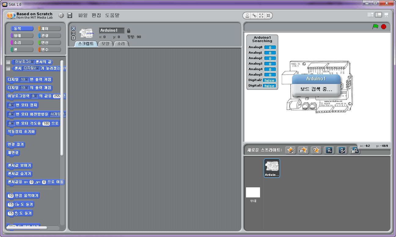
< 스크래치 1.6v, S4A 실행 화면>
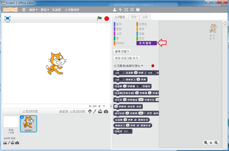
<스크래치 2.0v, S2A 실행 화면>
이전 컨텐츠에서 스크래치에 대해서 알아보고 스크래치와 아두이노와 연동할 수 있도록 만든 프로그램 Scratch for Arduino(S4A)를 설치해 보고, 추가로 LED 깜빡이기 / 게임 만들기 를 해보았습니다.
이번에는 스크래치와 아두이노 연동 프로그램인 Snap for Arduino(S2A)를 설치하여 스크래치와 아두이노를 연결하고 제어해보겠습니다.
- S4A는 스크래치, S2A_fm 은 스크래치2와 연동을 합니다.(위의 이미지를 참고하세요)
- S2A는 기존 firmata를 사용하기 때문에 스크래치와 아두이노간 전송되는 데이터를 정확하게 파악 할 수 있고, 추후 다른 장비를 통하여 원격지의 아두이노의 제어가 가능합니다.
- S4A와 다르게 S2A는 설치가 복잡하고 설치 후에도 실행하기 위해 두단계 절차를 진행해야 합니다.
- 한정적인 I/O 핀을 사용하는 S4A와는 다르게 S2A는 자신이 원하는 I/O 핀을 사용 할 수 있습니다.
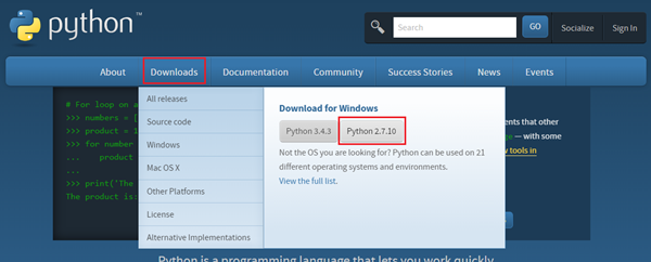
1. Pyhton을 설치합니다.(S2A_fm이 파이선을 사용하기 때문에 프로그램이 필요합니다.)
http://python.org에 들어가서 밑의 빨간 네모와 같이 Downloads -> Pythons2.7.10을 다운 받습니다.(이번 컨텐츠에서는 파이썬 버전 2.7.10을 사용합니다.)
다운이 받아지면 실행하여 Python을 설치해 줍니다.
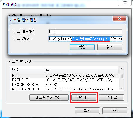
2. 설치가 다되었으면 컴퓨터 속성 -> 고급 시스템 속성 -> 고급 -> 환경 변수에 들어 갑니다.
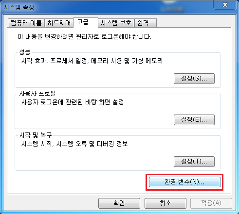
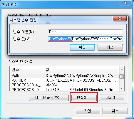
3. 시스템 변수(밑의 칸)에서 Path를 찾아서 편집 버튼을 눌러 줍니다. 그리고 맨 앞에 D:\Python27; 를 넣어 줍니다.(Python을 설치한 폴더를 입력하신 후 마지막에 ; 를 넣어주시면 됩니다.)
(* 참고로 Python이 설치 된 주소는 기본은 C:\Python27입니다. 내 컴퓨터에서 Python을 설치한 폴더에 들어가서 위에 주소창을 누르시면 해당 위치의 주소가 선택이 됩니다.)
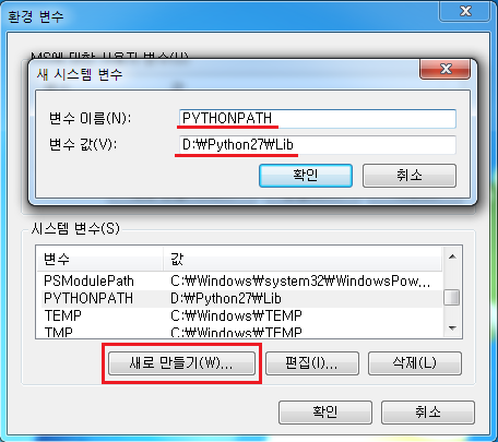
그 다음 새로만들기 버튼을 누른 후 변수 이름에 PYTHONPATH, 변수 값에 D:\Python27\Lib 를 넣어 줍니다.(위와 마찬가지로 Python이 설치된 폴더 안에 Lib폴더 위치를 넣어 주시면 됩니다.)
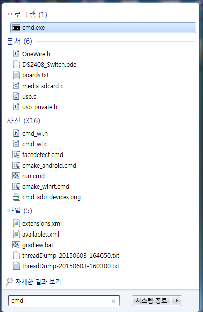
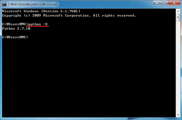
4. Path 설정이 완료 되었으면 cmd를 실행해 줍니다. (윈도우키 + r 을 누르셔서 실행을 키신 후 cmd를 입력하셔도 됩니다.)
cmd 창에서 python -V 를 입력하면 설치된 Python의 버전을 확인 할 수 있습니다.(설치가 제대로 되지 않을 경우 에러 메세지가 나옵니다.)
Python 설치가 완료되었으면 이번엔 setuptools을 받아 pip를 설치하고, PySerial과 PyMata를 설치해 보겠습니다.
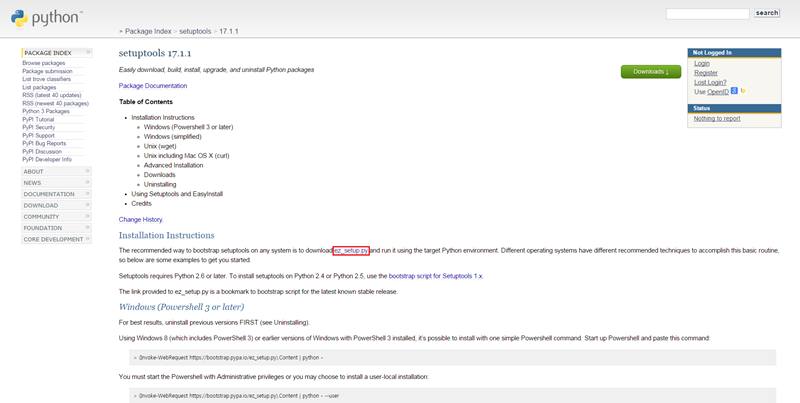
5. 우선 https://pypi.python.org/pypi/setuptools/ 에 들어가셔서 ez_setup.py 를 받습니다.(중간에 다운받는 링크가 있습니다.)
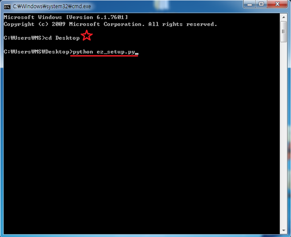
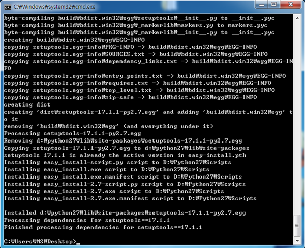
6. 그다음 cmd창에서 python ez_setup.py 명령어를 입력해줍니다.(꼭 ez_setup.py 가 설치된 폴더에서 입력해야 합니다. 전 별표에 보이는것 처럼 바탕화면에 받아서 바탕화면으로 이동 후 설치하였습니다.)
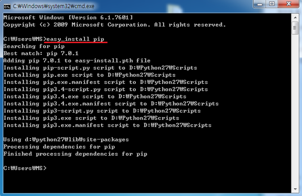
7. 설치가 다 되셧으면 다시 환경 변수로 가서 Path에 D:\Python27\Scripts; 를 넣어 줍니다.(위에 3번과 같이 현재 Python이 설치된 폴더를 기준으로 입력하셔야 합니다. Python폴더 안에 Scripts 폴더 주소를 넣어주시면 됩니다.)
8. Path 설정이 되셧으면 다시 cmd를 열고 easy_install pip 명령어를 입력해줍니다.(추가로 환경 변수 설정을 하신 후 cmd창을 다시 실행 하셔야 적용됩니다.)
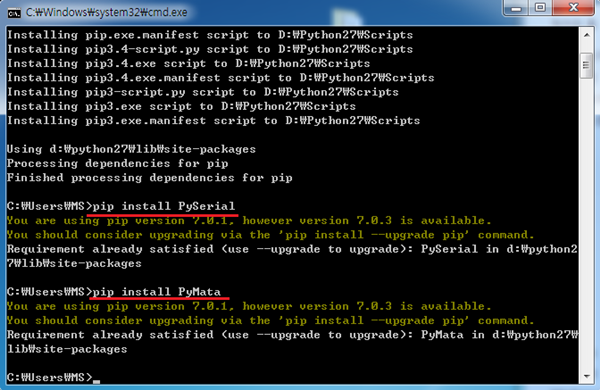
9. pip 설치가 완료되셧으면 pip install PySerial / pip install PyMata 명령어를 이용하여 PySerial과 Pymata를 설치해 주시면 됩니다.
(밑의 사진은 이미 설치된 컴퓨터라서 재설치를 안하는 것이고 처음 설치하시면 제대로 설치 과정이 진행 됩니다.)
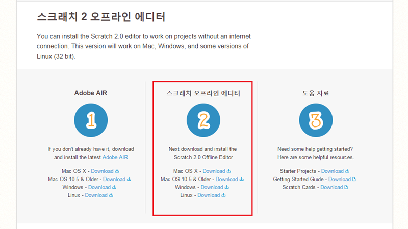
PySerial과 Pymata가 설치 되셧으면 이젠 직접 사용할 스크래치2를 설치해 보겠습니다.
10. http://scratch.mit.edu/scratch2download/ 홉페이지에 들어가셔서 2번 스크래치 오프라인 에디터를 자신의 컴퓨터 OS에 맞게 받고 설치 합니다.
( 1번 Adobe AIR는 스크래치 설치중에 자동으로 설치 됩니다.)
이제 직접 사용할 스크래치2도 설치 했으니 마지막으로 아두이노 세팅을 한후 스크래치와 연동해보도록 하겠습니다.
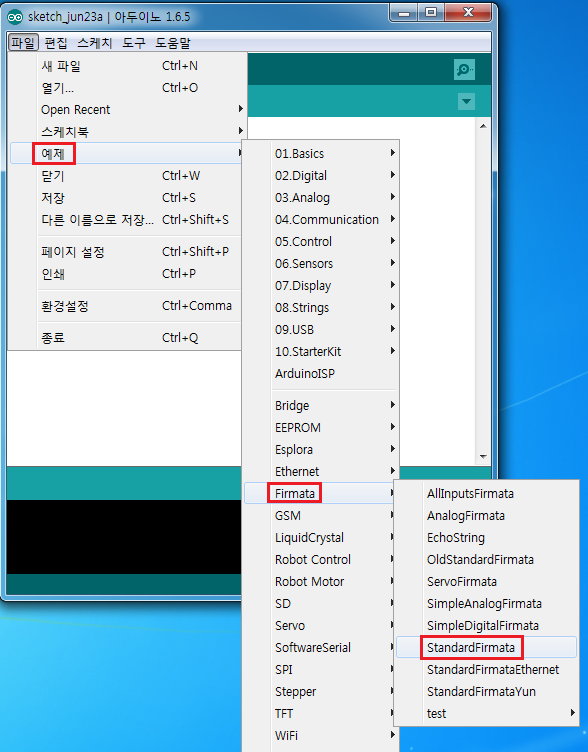
11. 우선 아두이노를 컴퓨터와 연결 후(시리얼 포트 번호를 꼭 확인하세요, 나중에 스크래치와 연동시 필요합니다.) 스케치에서 예제 -> Firmata -> StamdardFirmata 예제를 불러 온 후 아두이노에 업로드 합니다.
(따로 작업하실 것 없이 저 예제 파일만 업로드하시면 됩니다.)
/*
  Firmata is a generic protocol for communicating with microcontrollers
  from software on a host computer. It is intended to work with
  any host computer software package.

  To download a host software package, please clink on the following link
  to open the download page in your default browser.

  https://github.com/firmata/arduino#firmata-client-libraries

  Copyright (C) 2006-2008 Hans-Christoph Steiner.  All rights reserved.
  Copyright (C) 2010-2011 Paul Stoffregen.  All rights reserved.
  Copyright (C) 2009 Shigeru Kobayashi.  All rights reserved.
  Copyright (C) 2009-2015 Jeff Hoefs.  All rights reserved.

  This library is free software; you can redistribute it and/or
  modify it under the terms of the GNU Lesser General Public
  License as published by the Free Software Foundation; either
  version 2.1 of the License, or (at your option) any later version.

  See file LICENSE.txt for further informations on licensing terms.

  Last updated by Jeff Hoefs: April 11, 2015
*/

#include <Servo.h>
#include <Wire.h>
#include <Firmata.h>

#define I2C_WRITE                   B00000000
#define I2C_READ                    B00001000
#define I2C_READ_CONTINUOUSLY       B00010000
#define I2C_STOP_READING            B00011000
#define I2C_READ_WRITE_MODE_MASK    B00011000
#define I2C_10BIT_ADDRESS_MODE_MASK B00100000
#define MAX_QUERIES                 8
#define REGISTER_NOT_SPECIFIED      -1

// the minimum interval for sampling analog input
#define MINIMUM_SAMPLING_INTERVAL 10


/*==============================================================================
 * GLOBAL VARIABLES
 *============================================================================*/

/* analog inputs */
int analogInputsToReport = 0; // bitwise array to store pin reporting

/* digital input ports */
byte reportPINs[TOTAL_PORTS];       // 1 = report this port, 0 = silence
byte previousPINs[TOTAL_PORTS];     // previous 8 bits sent

/* pins configuration */
byte pinConfig[TOTAL_PINS];         // configuration of every pin
byte portConfigInputs[TOTAL_PORTS]; // each bit: 1 = pin in INPUT, 0 = anything else
int pinState[TOTAL_PINS];           // any value that has been written

/* timer variables */
unsigned long currentMillis;        // store the current value from millis()
unsigned long previousMillis;       // for comparison with currentMillis
unsigned int samplingInterval = 19; // how often to run the main loop (in ms)

/* i2c data */
struct i2c_device_info {
	byte addr;
	int reg;
	byte bytes;
};

/* for i2c read continuous more */
i2c_device_info query[MAX_QUERIES];

byte i2cRxData[32];
boolean isI2CEnabled = false;
signed char queryIndex = -1;
// default delay time between i2c read request and Wire.requestFrom()
unsigned int i2cReadDelayTime = 0;

Servo servos[MAX_SERVOS];
byte servoPinMap[TOTAL_PINS];
byte detachedServos[MAX_SERVOS];
byte detachedServoCount = 0;
byte servoCount = 0;

boolean isResetting = false;

/* utility functions */
void wireWrite(byte data) {
#if ARDUINO >= 100
	Wire.write((byte)data);
#else
	Wire.send(data);
#endif
}

byte wireRead(void) {
#if ARDUINO >= 100
	return Wire.read();
#else
	return Wire.receive();
#endif
}

/*==============================================================================
 * FUNCTIONS
 *============================================================================*/

void attachServo(byte pin, int minPulse, int maxPulse) {
	if (servoCount < MAX_SERVOS) {
		// reuse indexes of detached servos until all have been reallocated
		if (detachedServoCount > 0) {
			servoPinMap[pin] = detachedServos[detachedServoCount - 1];
			if (detachedServoCount > 0) detachedServoCount--;
		} else {
			servoPinMap[pin] = servoCount;
			servoCount++;
		}

		if (minPulse > 0 && maxPulse > 0) {
      		servos[servoPinMap[pin]].attach(PIN_TO_DIGITAL(pin), minPulse, maxPulse);
		} else {
			servos[servoPinMap[pin]].attach(PIN_TO_DIGITAL(pin));
		}

	} else {
		Firmata.sendString("Max servos attached");
	}
}

void detachServo(byte pin) {
	servos[servoPinMap[pin]].detach();
	// if we're detaching the last servo, decrement the count
	// otherwise store the index of the detached servo
	if (servoPinMap[pin] == servoCount && servoCount > 0) {
		servoCount--;
	} else if (servoCount > 0) {
		// keep track of detached servos because we want to reuse their indexes
		// before incrementing the count of attached servos
		detachedServoCount++;
		detachedServos[detachedServoCount - 1] = servoPinMap[pin];
	}

	servoPinMap[pin] = 255;
}

void readAndReportData(byte address, int theRegister, byte numBytes) {
	// allow I2C requests that don't require a register read
	// for example, some devices using an interrupt pin to signify new data available
	// do not always require the register read so upon interrupt you call Wire.requestFrom()
	if (theRegister != REGISTER_NOT_SPECIFIED) {
		Wire.beginTransmission(address);
		wireWrite((byte)theRegister);
		Wire.endTransmission();
		// do not set a value of 0
		if (i2cReadDelayTime > 0) {
			// delay is necessary for some devices such as WiiNunchuck
			delayMicroseconds(i2cReadDelayTime);
		}
	} else {
		theRegister = 0;  // fill the register with a dummy value
	}

	Wire.requestFrom(address, numBytes);  // all bytes are returned in requestFrom

	// check to be sure correct number of bytes were returned by slave
	if (numBytes < Wire.available()) {
		Firmata.sendString("I2C: Too many bytes received");
	} else if (numBytes > Wire.available()) {
		Firmata.sendString("I2C: Too few bytes received");
	}

	i2cRxData[0] = address;
	i2cRxData[1] = theRegister;

	for (int i = 0; i < numBytes && Wire.available(); i++) {
		i2cRxData[2 + i] = wireRead();
	}

	// send slave address, register and received bytes
	Firmata.sendSysex(SYSEX_I2C_REPLY, numBytes + 2, i2cRxData);
}

void outputPort(byte portNumber, byte portValue, byte forceSend) {
	// pins not configured as INPUT are cleared to zeros
	portValue = portValue & portConfigInputs[portNumber];
	// only send if the value is different than previously sent
	if (forceSend || previousPINs[portNumber] != portValue) {
		Firmata.sendDigitalPort(portNumber, portValue);
		previousPINs[portNumber] = portValue;
	}
}

/* -----------------------------------------------------------------------------
 * check all the active digital inputs for change of state, then add any events
 * to the Serial output queue using Serial.print() */
void checkDigitalInputs(void) {
	/* Using non-looping code allows constants to be given to readPort().
	 * The compiler will apply substantial optimizations if the inputs
	 * to readPort() are compile-time constants. */
	if (TOTAL_PORTS > 0 && reportPINs[0]) outputPort(0, readPort(0, portConfigInputs[0]), false);
	if (TOTAL_PORTS > 1 && reportPINs[1]) outputPort(1, readPort(1, portConfigInputs[1]), false);
	if (TOTAL_PORTS > 2 && reportPINs[2]) outputPort(2, readPort(2, portConfigInputs[2]), false);
	if (TOTAL_PORTS > 3 && reportPINs[3]) outputPort(3, readPort(3, portConfigInputs[3]), false);
	if (TOTAL_PORTS > 4 && reportPINs[4]) outputPort(4, readPort(4, portConfigInputs[4]), false);
	if (TOTAL_PORTS > 5 && reportPINs[5]) outputPort(5, readPort(5, portConfigInputs[5]), false);
	if (TOTAL_PORTS > 6 && reportPINs[6]) outputPort(6, readPort(6, portConfigInputs[6]), false);
	if (TOTAL_PORTS > 7 && reportPINs[7]) outputPort(7, readPort(7, portConfigInputs[7]), false);
	if (TOTAL_PORTS > 8 && reportPINs[8]) outputPort(8, readPort(8, portConfigInputs[8]), false);
	if (TOTAL_PORTS > 9 && reportPINs[9]) outputPort(9, readPort(9, portConfigInputs[9]), false);
	if (TOTAL_PORTS > 10 && reportPINs[10]) outputPort(10, readPort(10, portConfigInputs[10]), false);
	if (TOTAL_PORTS > 11 && reportPINs[11]) outputPort(11, readPort(11, portConfigInputs[11]), false);
	if (TOTAL_PORTS > 12 && reportPINs[12]) outputPort(12, readPort(12, portConfigInputs[12]), false);
	if (TOTAL_PORTS > 13 && reportPINs[13]) outputPort(13, readPort(13, portConfigInputs[13]), false);
	if (TOTAL_PORTS > 14 && reportPINs[14]) outputPort(14, readPort(14, portConfigInputs[14]), false);
	if (TOTAL_PORTS > 15 && reportPINs[15]) outputPort(15, readPort(15, portConfigInputs[15]), false);
}

// -----------------------------------------------------------------------------
/* sets the pin mode to the correct state and sets the relevant bits in the
 * two bit-arrays that track Digital I/O and PWM status
 */
void setPinModeCallback(byte pin, int mode) {

	if (pinConfig[pin] == I2C && isI2CEnabled && mode != I2C) {
		// disable i2c so pins can be used for other functions
		// the following if statements should reconfigure the pins properly
		disableI2CPins();
	}
	if (IS_PIN_DIGITAL(pin) && mode != SERVO) {
		if (servoPinMap[pin] < MAX_SERVOS && servos[servoPinMap[pin]].attached()) {
			detachServo(pin);
		}
	}
	if (IS_PIN_ANALOG(pin)) {
		reportAnalogCallback(PIN_TO_ANALOG(pin), mode == ANALOG ? 1 : 0); // turn on/off reporting
	}
	if (IS_PIN_DIGITAL(pin)) {
		if (mode == INPUT) {
			portConfigInputs[pin / 8] |= (1 << (pin & 7));
		} else {
			portConfigInputs[pin / 8] &= ~(1 << (pin & 7));
		}
  	}

	pinState[pin] = 0;
	switch (mode) {
	case ANALOG:
		if (IS_PIN_ANALOG(pin)) {
			if (IS_PIN_DIGITAL(pin)) {
				pinMode(PIN_TO_DIGITAL(pin), INPUT);    // disable output driver
				digitalWrite(PIN_TO_DIGITAL(pin), LOW); // disable internal pull-ups
			}
			pinConfig[pin] = ANALOG;
		}
		break;
	case INPUT:
		if (IS_PIN_DIGITAL(pin)) {
			pinMode(PIN_TO_DIGITAL(pin), INPUT);    // disable output driver
			digitalWrite(PIN_TO_DIGITAL(pin), LOW); // disable internal pull-ups
			pinConfig[pin] = INPUT;
		}
		break;
	case OUTPUT:
		if (IS_PIN_DIGITAL(pin)) {
			digitalWrite(PIN_TO_DIGITAL(pin), LOW); // disable PWM
			pinMode(PIN_TO_DIGITAL(pin), OUTPUT);
			pinConfig[pin] = OUTPUT;
		}
		break;
	case PWM:
		if (IS_PIN_PWM(pin)) {
			pinMode(PIN_TO_PWM(pin), OUTPUT);
			analogWrite(PIN_TO_PWM(pin), 0);
			pinConfig[pin] = PWM;
		}
		break;
	case SERVO:
		if (IS_PIN_DIGITAL(pin)) {
			pinConfig[pin] = SERVO;
			if (servoPinMap[pin] == 255 || !servos[servoPinMap[pin]].attached()) {
				// pass -1 for min and max pulse values to use default values set
				// by Servo library
				attachServo(pin, -1, -1);
			}
		}
		break;
	case I2C:
		if (IS_PIN_I2C(pin)) {
			// mark the pin as i2c
			// the user must call I2C_CONFIG to enable I2C for a device
			pinConfig[pin] = I2C;
		}
		break;
	default:
		Firmata.sendString("Unknown pin mode"); // TODO: put error msgs in EEPROM
	}
	// TODO: save status to EEPROM here, if changed
}

void analogWriteCallback(byte pin, int value) {
	if (pin < TOTAL_PINS) {
		switch (pinConfig[pin]) {
		case SERVO:
			if (IS_PIN_DIGITAL(pin)) {
				servos[servoPinMap[pin]].write(value);
			}
			pinState[pin] = value;
			break;
		case PWM:
			if (IS_PIN_PWM(pin)) {
				analogWrite(PIN_TO_PWM(pin), value);
			}
			pinState[pin] = value;
			break;
		}
	}
}

void digitalWriteCallback(byte port, int value) {
	byte pin, lastPin, mask = 1, pinWriteMask = 0;

	if (port < TOTAL_PORTS) {
		// create a mask of the pins on this port that are writable.
		lastPin = port * 8 + 8;
		if (lastPin > TOTAL_PINS) {
			lastPin = TOTAL_PINS;
		}
		for (pin = port * 8; pin < lastPin; pin++) {
			// do not disturb non-digital pins (eg, Rx & Tx)
			if (IS_PIN_DIGITAL(pin)) {
				// only write to OUTPUT and INPUT (enables pullup)
				// do not touch pins in PWM, ANALOG, SERVO or other modes
				if (pinConfig[pin] == OUTPUT || pinConfig[pin] == INPUT) {
					pinWriteMask |= mask;
					pinState[pin] = ((byte)value & mask) ? 1 : 0;
				}
			}
			mask = mask << 1;
		}
		writePort(port, (byte)value, pinWriteMask);
	}
}


// -----------------------------------------------------------------------------
/* sets bits in a bit array (int) to toggle the reporting of the analogIns
 */
//void FirmataClass::setAnalogPinReporting(byte pin, byte state) {
//}
void reportAnalogCallback(byte analogPin, int value) {
	if (analogPin < TOTAL_ANALOG_PINS) {
		if (value == 0) {
			analogInputsToReport = analogInputsToReport & ~ (1 << analogPin);
		} else {
			analogInputsToReport = analogInputsToReport | (1 << analogPin);
			// prevent during system reset or all analog pin values will be reported
			// which may report noise for unconnected analog pins
			if (!isResetting) {
				// Send pin value immediately. This is helpful when connected via
				// ethernet, wi-fi or bluetooth so pin states can be known upon
				// reconnecting.
				Firmata.sendAnalog(analogPin, analogRead(analogPin));
			}
		}
	}
	// TODO: save status to EEPROM here, if changed
}

void reportDigitalCallback(byte port, int value) {
	if (port < TOTAL_PORTS) {
		reportPINs[port] = (byte)value;
		// Send port value immediately. This is helpful when connected via
		// ethernet, wi-fi or bluetooth so pin states can be known upon
		// reconnecting.
		if (value) outputPort(port, readPort(port, portConfigInputs[port]), true);
	}
	// do not disable analog reporting on these 8 pins, to allow some
	// pins used for digital, others analog.  Instead, allow both types
	// of reporting to be enabled, but check if the pin is configured
	// as analog when sampling the analog inputs.  Likewise, while
	// scanning digital pins, portConfigInputs will mask off values from any
	// pins configured as analog
}

/*==============================================================================
 * SYSEX-BASED commands
 *============================================================================*/

void sysexCallback(byte command, byte argc, byte *argv) {
	byte mode;
	byte slaveAddress;
	byte data;
	int slaveRegister;
	unsigned int delayTime;

	switch (command) {
	case I2C_REQUEST:
		mode = argv[1] & I2C_READ_WRITE_MODE_MASK;
		if (argv[1] & I2C_10BIT_ADDRESS_MODE_MASK) {
			Firmata.sendString("10-bit addressing not supported");
			return;
		} else {
			slaveAddress = argv[0];
		}

		switch (mode) {
		case I2C_WRITE:
			Wire.beginTransmission(slaveAddress);
			for (byte i = 2; i < argc; i += 2) {
				data = argv[i] + (argv[i + 1] << 7);
				wireWrite(data);
			}
			Wire.endTransmission();
			delayMicroseconds(70);
			break;
		case I2C_READ:
			if (argc == 6) {
				// a slave register is specified
				slaveRegister = argv[2] + (argv[3] << 7);
				data = argv[4] + (argv[5] << 7);  // bytes to read
			} else {
				// a slave register is NOT specified
				slaveRegister = REGISTER_NOT_SPECIFIED;
				data = argv[2] + (argv[3] << 7);  // bytes to read
			}
			readAndReportData(slaveAddress, (int)slaveRegister, data);
			break;
		case I2C_READ_CONTINUOUSLY:
			if ((queryIndex + 1) >= MAX_QUERIES) {
				// too many queries, just ignore
				Firmata.sendString("too many queries");
				break;
			}
			if (argc == 6) {
				// a slave register is specified
				slaveRegister = argv[2] + (argv[3] << 7);
				data = argv[4] + (argv[5] << 7);  // bytes to read
			} else {
				// a slave register is NOT specified
				slaveRegister = (int)REGISTER_NOT_SPECIFIED;
				data = argv[2] + (argv[3] << 7);  // bytes to read
			}
			queryIndex++;
			query[queryIndex].addr = slaveAddress;
			query[queryIndex].reg = slaveRegister;
			query[queryIndex].bytes = data;
			break;
		case I2C_STOP_READING:
			byte queryIndexToSkip;
			// if read continuous mode is enabled for only 1 i2c device, disable
			// read continuous reporting for that device
			if (queryIndex <= 0) {
				queryIndex = -1;
			} else {
				// if read continuous mode is enabled for multiple devices,
				// determine which device to stop reading and remove it's data from
				// the array, shifiting other array data to fill the space
				for (byte i = 0; i < queryIndex + 1; i++) {
					if (query[i].addr == slaveAddress) {
						queryIndexToSkip = i;
						break;
					}
				}

				for (byte i = queryIndexToSkip; i < queryIndex + 1; i++) {
					if (i < MAX_QUERIES) {
						query[i].addr = query[i + 1].addr;
						query[i].reg = query[i + 1].reg;
						query[i].bytes = query[i + 1].bytes;
					}
				}
				queryIndex--;
			}
			break;
		default:
			break;
		}
		break;
	case I2C_CONFIG:
		delayTime = (argv[0] + (argv[1] << 7));
		if (delayTime > 0) {
			i2cReadDelayTime = delayTime;
		}
		if (!isI2CEnabled) {
			enableI2CPins();
		}
		break;
	case SERVO_CONFIG:
		if (argc > 4) {
			// these vars are here for clarity, they'll optimized away by the compiler
			byte pin = argv[0];
			int minPulse = argv[1] + (argv[2] << 7);
			int maxPulse = argv[3] + (argv[4] << 7);

			if (IS_PIN_DIGITAL(pin)) {
				if (servoPinMap[pin] < MAX_SERVOS && servos[servoPinMap[pin]].attached()) {
					detachServo(pin);
				}
				attachServo(pin, minPulse, maxPulse);
				setPinModeCallback(pin, SERVO);
			}
		}
		break;
	case SAMPLING_INTERVAL:
		if (argc > 1) {
			samplingInterval = argv[0] + (argv[1] << 7);
			if (samplingInterval < MINIMUM_SAMPLING_INTERVAL) {
				samplingInterval = MINIMUM_SAMPLING_INTERVAL;
			}
		} else {
			//Firmata.sendString("Not enough data");
		}
		break;
	case EXTENDED_ANALOG:
		if (argc > 1) {
			int val = argv[1];
			if (argc > 2) val |= (argv[2] << 7);
			if (argc > 3) val |= (argv[3] << 14);
			analogWriteCallback(argv[0], val);
		}
		break;
	case CAPABILITY_QUERY:
		Serial.write(START_SYSEX);
		Serial.write(CAPABILITY_RESPONSE);
		for (byte pin = 0; pin < TOTAL_PINS; pin++) {
			if (IS_PIN_DIGITAL(pin)) {
				Serial.write((byte)INPUT);
				Serial.write(1);
				Serial.write((byte)OUTPUT);
				Serial.write(1);
			}
			if (IS_PIN_ANALOG(pin)) {
				Serial.write(ANALOG);
				Serial.write(10); // 10 = 10-bit resolution
			}
			if (IS_PIN_PWM(pin)) {
				Serial.write(PWM);
				Serial.write(8); // 8 = 8-bit resolution
			}
			if (IS_PIN_DIGITAL(pin)) {
				Serial.write(SERVO);
				Serial.write(14);
			}
			if (IS_PIN_I2C(pin)) {
				Serial.write(I2C);
				Serial.write(1);  // TODO: could assign a number to map to SCL or SDA
			}
			Serial.write(127);
		}
		Serial.write(END_SYSEX);
		break;
	case PIN_STATE_QUERY:
		if (argc > 0) {
			byte pin = argv[0];
			Serial.write(START_SYSEX);
			Serial.write(PIN_STATE_RESPONSE);
			Serial.write(pin);
			if (pin < TOTAL_PINS) {
				Serial.write((byte)pinConfig[pin]);
				Serial.write((byte)pinState[pin] & 0x7F);
				if (pinState[pin] & 0xFF80) Serial.write((byte)(pinState[pin] >> 7) & 0x7F);
				if (pinState[pin] & 0xC000) Serial.write((byte)(pinState[pin] >> 14) & 0x7F);
			}
			Serial.write(END_SYSEX);
		}
		break;
	case ANALOG_MAPPING_QUERY:
		Serial.write(START_SYSEX);
		Serial.write(ANALOG_MAPPING_RESPONSE);
		for (byte pin = 0; pin < TOTAL_PINS; pin++) {
			Serial.write(IS_PIN_ANALOG(pin) ? PIN_TO_ANALOG(pin) : 127);
		}
		Serial.write(END_SYSEX);
		break;
	}
}

void enableI2CPins() {
	byte i;
	// is there a faster way to do this? would probaby require importing
	// Arduino.h to get SCL and SDA pins
	for (i = 0; i < TOTAL_PINS; i++) {
		if (IS_PIN_I2C(i)) {
			// mark pins as i2c so they are ignore in non i2c data requests
			setPinModeCallback(i, I2C);
		}
	}

	isI2CEnabled = true;

	Wire.begin();
}

/* disable the i2c pins so they can be used for other functions */
void disableI2CPins() {
	isI2CEnabled = false;
	// disable read continuous mode for all devices
	queryIndex = -1;
}

/*==============================================================================
 * SETUP()
 *============================================================================*/

void systemResetCallback() {
	isResetting = true;

	// initialize a defalt state
	// TODO: option to load config from EEPROM instead of default

	if (isI2CEnabled) {
		disableI2CPins();
	}

	for (byte i = 0; i < TOTAL_PORTS; i++) {
		reportPINs[i] = false;    // by default, reporting off
		portConfigInputs[i] = 0;  // until activated
		previousPINs[i] = 0;
	}

	for (byte i = 0; i < TOTAL_PINS; i++) {
		// pins with analog capability default to analog input
		// otherwise, pins default to digital output
		if (IS_PIN_ANALOG(i)) {
			// turns off pullup, configures everything
			setPinModeCallback(i, ANALOG);
		} else {
			// sets the output to 0, configures portConfigInputs
			setPinModeCallback(i, OUTPUT);
		}

		servoPinMap[i] = 255;
	}
	// by default, do not report any analog inputs
	analogInputsToReport = 0;

	detachedServoCount = 0;
	servoCount = 0;

	/* send digital inputs to set the initial state on the host computer,
	* since once in the loop(), this firmware will only send on change */
	/*
	TODO: this can never execute, since no pins default to digital input
	but it will be needed when/if we support EEPROM stored config
	for (byte i=0; i < TOTAL_PORTS; i++) {
	outputPort(i, readPort(i, portConfigInputs[i]), true);
	}
	*/
	isResetting = false;
}

void setup() {
	Firmata.setFirmwareVersion(FIRMATA_MAJOR_VERSION, FIRMATA_MINOR_VERSION);

	Firmata.attach(ANALOG_MESSAGE, analogWriteCallback);
	Firmata.attach(DIGITAL_MESSAGE, digitalWriteCallback);
	Firmata.attach(REPORT_ANALOG, reportAnalogCallback);
	Firmata.attach(REPORT_DIGITAL, reportDigitalCallback);
	Firmata.attach(SET_PIN_MODE, setPinModeCallback);
	Firmata.attach(START_SYSEX, sysexCallback);
	Firmata.attach(SYSTEM_RESET, systemResetCallback);

	Firmata.begin(57600);
	systemResetCallback();  // reset to default config
}

/*==============================================================================
 * LOOP()
 *============================================================================*/
void loop() {
	byte pin, analogPin;

	/* DIGITALREAD - as fast as possible, check for changes and output them to the
	* FTDI buffer using Serial.print()  */
	checkDigitalInputs();

	/* STREAMREAD - processing incoming messagse as soon as possible, while still
	* checking digital inputs.  */
	while (Firmata.available()) {
		Firmata.processInput();
	}

	// TODO - ensure that Stream buffer doesn't go over 60 bytes

	currentMillis = millis();
	if (currentMillis - previousMillis > samplingInterval) {
		previousMillis += samplingInterval;
		/* ANALOGREAD - do all analogReads() at the configured sampling interval */
		for (pin = 0; pin < TOTAL_PINS; pin++) {
			if (IS_PIN_ANALOG(pin) && pinConfig[pin] == ANALOG) {
				analogPin = PIN_TO_ANALOG(pin);
				if (analogInputsToReport & (1 << analogPin)) {
					Firmata.sendAnalog(analogPin, analogRead(analogPin));
				}
			}
		}
		// report i2c data for all device with read continuous mode enabled
		if (queryIndex > -1) {
			for (byte i = 0; i < queryIndex + 1; i++) {
				readAndReportData(query[i].addr, query[i].reg, query[i].bytes);
			}
		}
	}
}
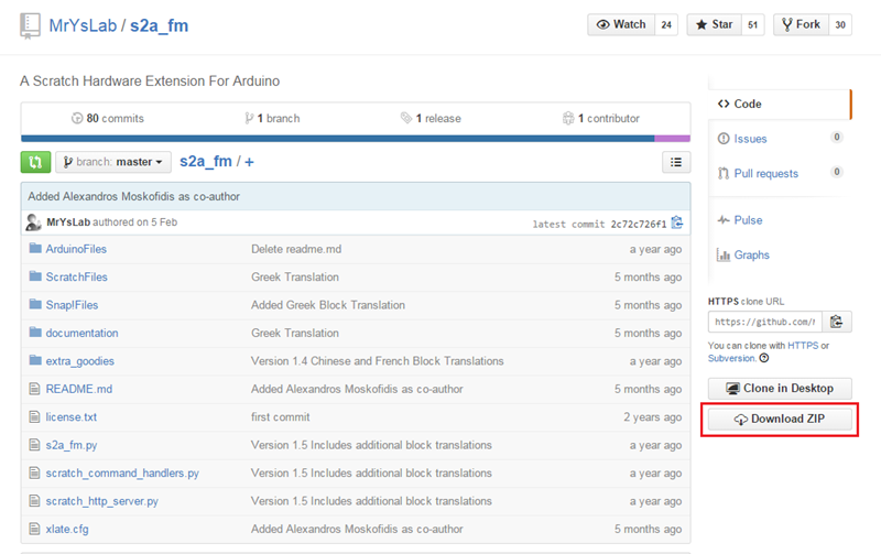
12. 그 후 https://github.com/MrYsLab/s2a_fm 여기에서 s2a_fm 파일을 받습니다.(밑의 네모칸에 있는 Download ZIP을 누르시면 됩니다.
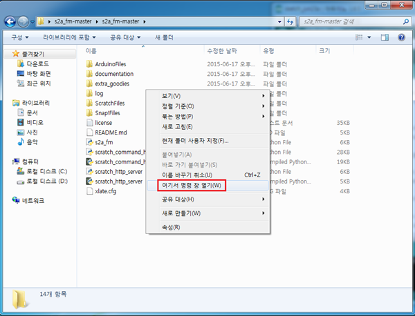
13. 다운 받으신 압축 파일의 압축을 풀고 폴더 안 빈공간에서 쉬프트 + 마우스 오른쪽 버튼을 누르시면 밑의 사진과 같이 여기서 명령 창 열기 메뉴가 나옵니다. 이것을 선택해 줍니다.
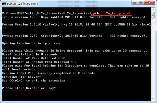
14. 그다음 python s2a_fm.py com3 을 입력해 주시면 아두이노와 스크래치 연동 준비가 끝나게 됩니다.(마지막 com3 부분에 현재 연결된 아두이노 포트 번호를 넣어주시면 됩니다.)
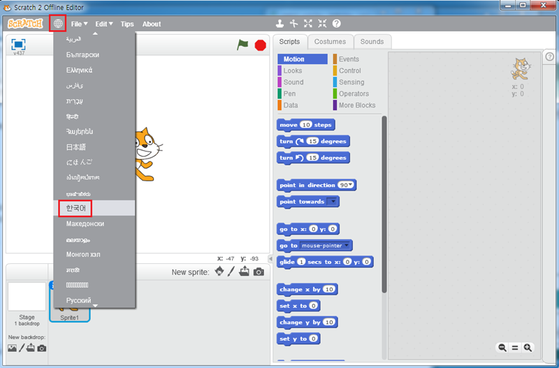
15. 위에서 받은 스크래치2를 실행하시면 밑의 화면과 같이 영문으로 나오게 됩니다. 한글로 바꾸실려면 네모칸에 있는 지구본 모양을 클릭 하신 후 밑으로 내리다 보면 한국어가 있습니다.
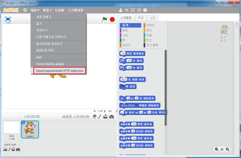
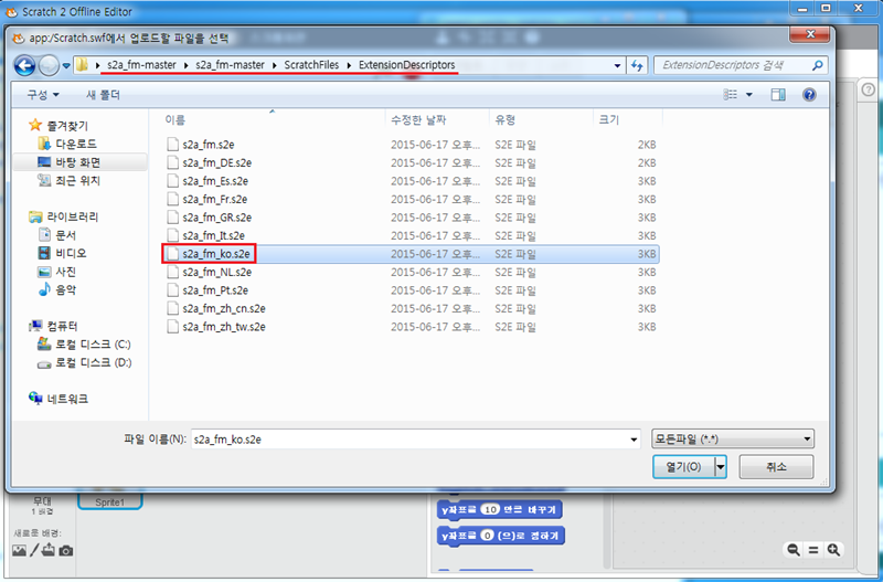
16. 한글로 설정 되셧으면 마지막으로 쉬프트 버튼을 누른채 파일 메뉴를 선택하시고 Import experimental HTTP extension 메뉴를 선택하신 후 github에서 받은 s2a_fm -> ScratchFiles -> ExtensionDescriptors 로 이동 하신 후 s2a_fm_ko.s2e 파일을 선택합니다.
17. 화살표에 있는 추가 블록 칸에 아두이노 제어 명령어 블록이 생겼습니다. 이것을 이용하여 다양하게 아두이노를 제어하시면 됩니다.


kocoafabeditor 
항상 진취적이고, 새로운 것을 추구하는 코코아팹 에디터입니다!
 스크래치, s2a_fm, 아두이노, 기타


